1. Introduzzjoni
This manual provides detailed instructions for the installation, operation, and maintenance of your visiPower SY828NH2IDEND2 2-Unit Visual Intercom Doorbell System. This system is designed for home and apartment use, offering secure visual communication and access control.
The SY828NH2IDEND2 system utilizes a 2-wire bus connection, simplifying installation by transmitting power, audio, video, and control signals through a single non-polarity cable. It supports up to two outdoor units and six indoor monitors, making it suitable for various configurations.
Karatteristiċi ewlenin:
- 2-Wire Bus System: Simplified wiring for power, audio, video, and control signals.
- Sistema espansibbli: Supports up to 2 outdoor units and 6 indoor monitors.
- Durable Outdoor Unit: Rain and oxidation-proof aluminum alloy with white LED night vision.
- 7-inch Color TFT LCD Monitor: High-definition display with adjustable brightness, contrast, and volume.
- Kontroll tas-Serratura Doppja: Ability to unlock two electronic door locks simultaneously.
- Hands-free Intercom: Convenient communication between indoor units and with the outdoor unit.
- RFID Access: Supports RFID keyfobs for door unlocking (5 keyfobs included).
- Door Monitoring: View the outdoor area from the indoor monitor.
2. Kontenut tal-Pakkett
Ivverifika li l-komponenti kollha elenkati hawn taħt huma preżenti fil-pakkett tiegħek:

Stampa 2.1: Fuqview of all included components for the visiPower SY828NH2IDEND2 system. This includes the outdoor camera unit, two indoor monitors, power supply, mounting screws, various connection wires, user manual, exit button, and electronic door lock.
- 1 x Outdoor Unit (Embedded mounted Camera)
- 2 x Indoor Unit (Monitor)
- 1 x DC24V 2.5A Power Supply
- 1 x Electronic Door Lock
- 1 x Exit Button
- 1 x 4-core Connection Lock Terminal Wire
- 1 x 2.54*2P 2-core Connection Terminal Wire
- 1 x 2.0*2P 2-core Connection Terminal Wire
- 1 x Viti u Plakek tal-Ħitan
- 1 x Manwal għall-Utent
- 5 x RFID Keyfobs (including add/delete keyfobs)
3. Setup u Installazzjoni
Careful installation is crucial for optimal performance. It is recommended to test the system components before permanent installation.
3.1. Dijagramma tal-Wajers
The system uses a 2-wire bus connection. Refer to the diagram below for proper wiring connections between the outdoor unit, indoor monitors, power supply, and electronic lock.

Stampa 3.1: Detailed wiring diagram illustrating the 2-wire bus connection. The outdoor unit connects to the power supply, which then connects to the indoor monitors. The electronic lock and exit button are also connected to the system.
- Connect the 2-wire bus cable from the outdoor unit to the power supply.
- Connect the power supply to the indoor monitors using the 2-wire bus cable.
- Connect the electronic door lock to the designated terminals on the outdoor unit or power supply, as indicated in the diagram.
- Connect the exit button to the appropriate terminals for internal door release.
- Ensure all connections are secure and correctly polarized (though the 2-wire bus is non-polarity, other connections might require attention).
3.2. Installazzjoni ta 'Unità ta' Barra
The outdoor unit is designed for embedded mounting. Ensure the mounting location provides a clear view of the entrance and is protected from direct heavy rain.

Stampa 3.2: Sploda view of the outdoor unit, highlighting its internal circuitry, camera lens, white LED for night vision, speaker, microphone, call buttons, RFID card reader, and DIP switches for configuration.
- Prepare an opening in the wall according to the embedded size specifications (118mm x 245mm x 38mm).
- Route the necessary wiring through the opening.
- Connect the 2-wire bus, electronic lock wires, and exit button wires to the outdoor unit's terminals as shown in the wiring diagram (Image 3.1) and component view (Immaġni 3.2).
- Secure the outdoor unit into the prepared opening using the provided screws.
3.3. Indoor Monitor Installation
The indoor monitors can be desk-mounted or wall-mounted.

Stampa 3.3: Rear and side panel details of the indoor monitor, indicating the location of the DIP switches, BUS connection, menu buttons, and volume controls.
- Choose a suitable location for the indoor monitor, ensuring it is within reach and provides clear visibility.
- For wall mounting, secure the hanging mount to the wall using screws.
- Connect the 2-wire bus cable to the BUS terminal on the back of the monitor (refer to Image 3.3).
- Mount the monitor onto the hanging mount or place it on a desk.
3.4. Konnessjoni tal-Provvista tal-Enerġija
Connect the DC24V 2.5A power supply to a standard AC 100-240V outlet. Ensure the power supply is connected to the system's main bus line as per the wiring diagram.

Stampa 3.4: The system's switching power supply, detailing its AC input and DC output terminals, and its compatibility with an electric box rail for secure installation.
4. Istruzzjonijiet Operattivi
4.1. Indoor Monitor Functions
Stampa 4.1: Front panel of the indoor monitor, showing the various buttons and indicators for operation.
- Buttuna tal-monitor: Agħfas biex view the live feed from the outdoor camera.
- Unlock 1 Button: Press to unlock the primary electronic door lock.
- Unlock 2 Button: Press to unlock the secondary electronic door lock (if connected).
- Talk/Intercom Button:
- When a visitor presses the call button on the outdoor unit, the indoor monitor will ring. Press this button to establish two-way communication.
- Press this button to initiate intercom communication with other indoor monitors in the system.
- Aġġustament tal-Volum: Use the 'Talk Volume' and 'Ring Volume' controls on the side of the monitor (refer to Image 3.3) to adjust audio levels.
- Luminożità/Kuntrast: Adjust these settings via the monitor's menu (accessed via menu buttons on the side, Image 3.3) for optimal display quality.
- Tfixkilx: Activate the 'Do Not Disturb' switch on the side of the monitor (Image 3.3) to silence incoming calls.
4.2. Outdoor Unit Operation
- Call Buttons: Visitors press the call button(s) to initiate a call to the indoor monitor(s).
- RFID Card Reader: Present an authorized RFID keyfob to the RFID card reader area to unlock the connected electronic door lock.
- Viżjoni bil-lejl: The integrated white LEDs automatically activate in low-light conditions to provide clear night vision.
4.3. RFID Keyfob Management
The system includes 5 RFID keyfobs: an 'Add Card', a 'Delete Card', and 3 user keyfobs. Additional user keyfobs can be programmed.
- Adding a Keyfob: Present the 'Add Card' to the outdoor unit's RFID reader. The system will enter programming mode. Then, present each new user keyfob you wish to add. Present the 'Add Card' again to exit programming mode.
- Deleting a Keyfob: Present the 'Delete Card' to the outdoor unit's RFID reader. The system will enter programming mode. Then, present each user keyfob you wish to delete. Present the 'Delete Card' again to exit programming mode.
5. Manutenzjoni
- Tindif: Uża artab, damp cloth to clean the surfaces of the outdoor unit and indoor monitors. Avoid abrasive cleaners or solvents.
- Unità ta 'barra: Periodically check the outdoor unit for any obstructions to the camera lens or microphone/speaker. Ensure the unit remains securely mounted.
- Wiring: Occasionally inspect visible wiring for any signs of damage or loose connections.
6 Issolvi l-problemi
If you encounter issues with your visiPower intercom system, refer to the following common troubleshooting steps:
| Problema | Kawża Possibbli | Soluzzjoni |
|---|---|---|
| No image on indoor monitor. | No power to the system; loose video cable connection; faulty outdoor unit camera. | Check power supply connection and outlet. Verify 2-wire bus connections. Inspect outdoor unit for damage. |
| No audio during intercom. | Loose audio cable connection; microphone/speaker obstruction; volume set too low. | Check 2-wire bus connections. Ensure no obstructions on outdoor unit or monitor. Adjust volume settings on the indoor monitor. |
| Il-lock tal-bieb ma jinfetaħx. | Incorrect wiring of electronic lock; insufficient power; faulty lock or unlock signal. | Verify electronic lock wiring according to diagram. Ensure power supply is adequate. Test with a different RFID keyfob if using RFID. |
| RFID keyfobs not working. | Keyfob not programmed; faulty RFID reader. | Ensure keyfobs are correctly programmed using the 'Add Card' procedure. Test with a known working keyfob. |
If the problem persists after attempting these solutions, please contact visiPower customer support for further assistance.
7. Speċifikazzjonijiet
Outdoor Camera Unit:
- Materjal: Liga tal-aluminju
- Kamera: 1/3" CMOS, 1000TV line
- View Angolu: 92°
- Viżjoni bil-lejl: LED abjad
- Konnessjoni: BUS 2-wire
- User Capacity (RFID): 2000 User Cards
- Tip ta' Karta: RFID compatible card, 125Khz
- Installazzjoni: Embedded mounted
- Dimensjonijiet: 265mm (L) x 128mm (W) x 48mm (H)
- Embedded Size: 118mm (L) x 245mm (W) x 38mm (H)
Monitor ta' ġewwa:
- Skrin: 7-il pulzier Kulur TFT LCD
- Pixels effettivi: 800 x 480
- Konnessjoni: BUS 2-wire
- Dimensjonijiet: 151mm (L) x 80mm (W) x 38mm (H)
Electronic Door Lock:
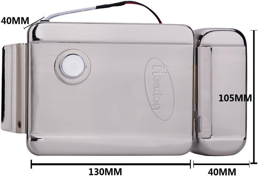
Stampa 7.1: Dimensions of the included electronic door lock.
- Ħidma Voltage: 12VDC
- Kurrent tax-Xogħol: 150mA
- Materjal: Azzar li ma jsaddadx
- Dimensjonijiet: 130mm (L) x 105mm (W) x 37mm (H)
- Ħin tal-Ħajja: 500,000 darba
Sistema Ġenerali:
- Sors tal-Enerġija: Corded Elettriku
- Provvista tal-Enerġija: DC24V 2.5A (Input: 100-240VAC)
- Teknoloġija tal-Konnettività: Wired (BUS 2-wire)
- Kulur: White (Monitors), Silver (Outdoor Unit)
- Piż tal-oġġett: Madwar 8 liri (pakkett totali)
- Dimensjonijiet tal-Prodott (Pakkett): 12 x 12.5 x 5.5 pulzieri
8. Garanzija u Appoġġ
For warranty information and technical support, please refer to the documentation provided with your purchase or contact visiPower customer service directly. Keep your purchase receipt as proof of purchase.
Manifattur: visiPower
For assistance, visit the official visiPower store or contact their support channels.
