1. Introduzzjoni
The Gikfun USB Cable Tester Board GK1030 is a versatile diagnostic tool designed for efficient testing of various USB and RJ45 network cables. It provides clear visual feedback via LED indicators, allowing users to quickly assess cable integrity, identify cable types, and detect potential faults. This manual provides detailed instructions for setting up and operating your cable tester.
2. Karatteristiċi tal-prodott
- Interface Type Identification: Supports testing for USB 3.2, USB 3.1, USB 3.0, Type-C, Micro-AB, Lightning, and RJ45 connectors.
- RJ45 Connector Testing: Capable of 8-core network cable continuity testing, displaying the status of each wire via indicators. Compatible with 100Mbps/1000Mbps network testing.
- Convenient and Practical: Features a portable design and compact size for ease of carrying and use.
- Dwal Indikaturi LED: Test results are clearly displayed through 24 LED indicators, with each pin corresponding to an LED light.
- Multi-funzjonali: Suitable for cable performance testing, electronic repair, device debugging, and cable procurement scenarios.
3. Kontenut tal-Pakkett
- 1 x Gikfun USB Cable Tester Board (GK1030)
Note: A DC 5V-12V power supply with a barrel jack connector is required for operation and is not included in the package.
4. Setup
4.1 Konnessjoni tal-Enerġija
To power the Gikfun USB Cable Tester Board, connect a DC 5V-12V power supply (not included) to the barrel jack input located at the top center of the board. Ensure the power supply is within the specified voltage firxa biex tevita ħsara lill-apparat.

Figure 4.1: Connecting the DC 5V-12V power source to the tester board.
5. Istruzzjonijiet Operattivi
The tester uses LED indicators to show the continuity and functionality of each pin within the connected cables. A lit LED indicates a successful connection for that specific pin.
5.1 USB Cable Testing
To test a USB cable, connect one end of the cable to the corresponding USB port on the left side of the tester (USB Type-A or USB Type-C) and the other end to the corresponding port on the right side (USB Type-C, Micro-AB, or Lightning). The LEDs will illuminate to indicate the status of each data and power line.
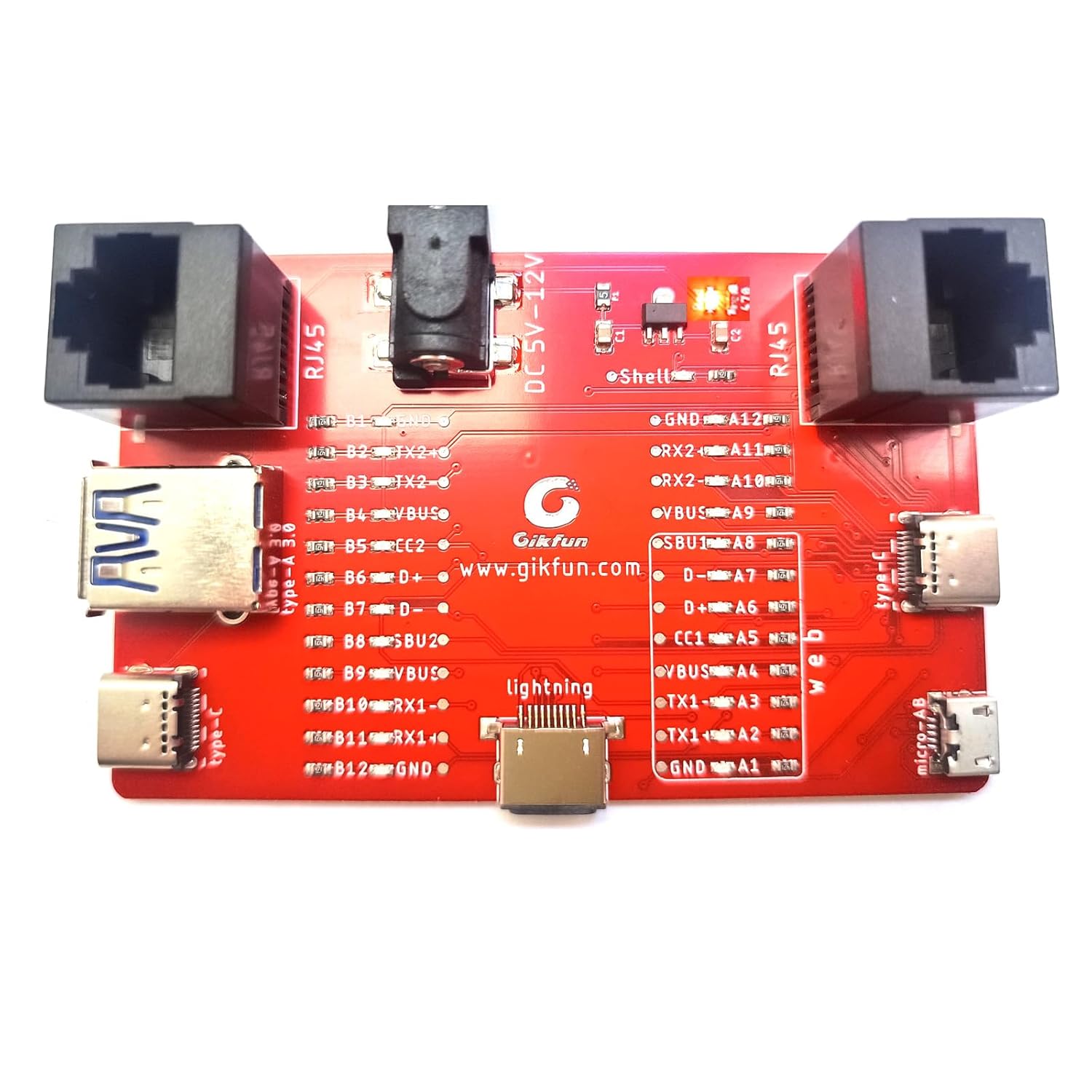
Figure 5.1: The tester board showing illuminated LEDs during a test.
5.1.1 Testing USB Type-C Cables
Connect both ends of the USB Type-C cable to the Type-C ports on the tester. Observe the LEDs for VBUS, GND, D+, D-, CC1, CC2, TX1, TX2, RX1, and RX2 to confirm full functionality, including data and charging capabilities.

Figure 5.1.1: USB Type-C cable connected for testing.
5.1.2 Testing Micro-AB USB Cables
Connect the Micro-AB end of the cable to the Micro-AB port on the right side and the other end (e.g., USB Type-A) to its corresponding port on the left. Check the LEDs for VBUS, GND, D+, and D-.

Figure 5.1.2: Micro-AB USB cable connected for testing.
5.1.3 Testing Lightning Cables
Connect the Lightning end of the cable to the Lightning port in the center and the other end (e.g., USB Type-A) to its corresponding port. Verify the LEDs for VBUS, GND, D+, and D-.

Figure 5.1.3: Lightning cable connected for testing.
5.2 RJ45 Network Cable Testing
Connect both ends of the RJ45 network cable to the RJ45 ports on the tester. The LEDs will indicate the continuity of each of the 8 cores. This helps identify if the cable supports 100Mbps (4 cores) or 1000Mbps (8 cores) connections and if any wires are broken or miswired.
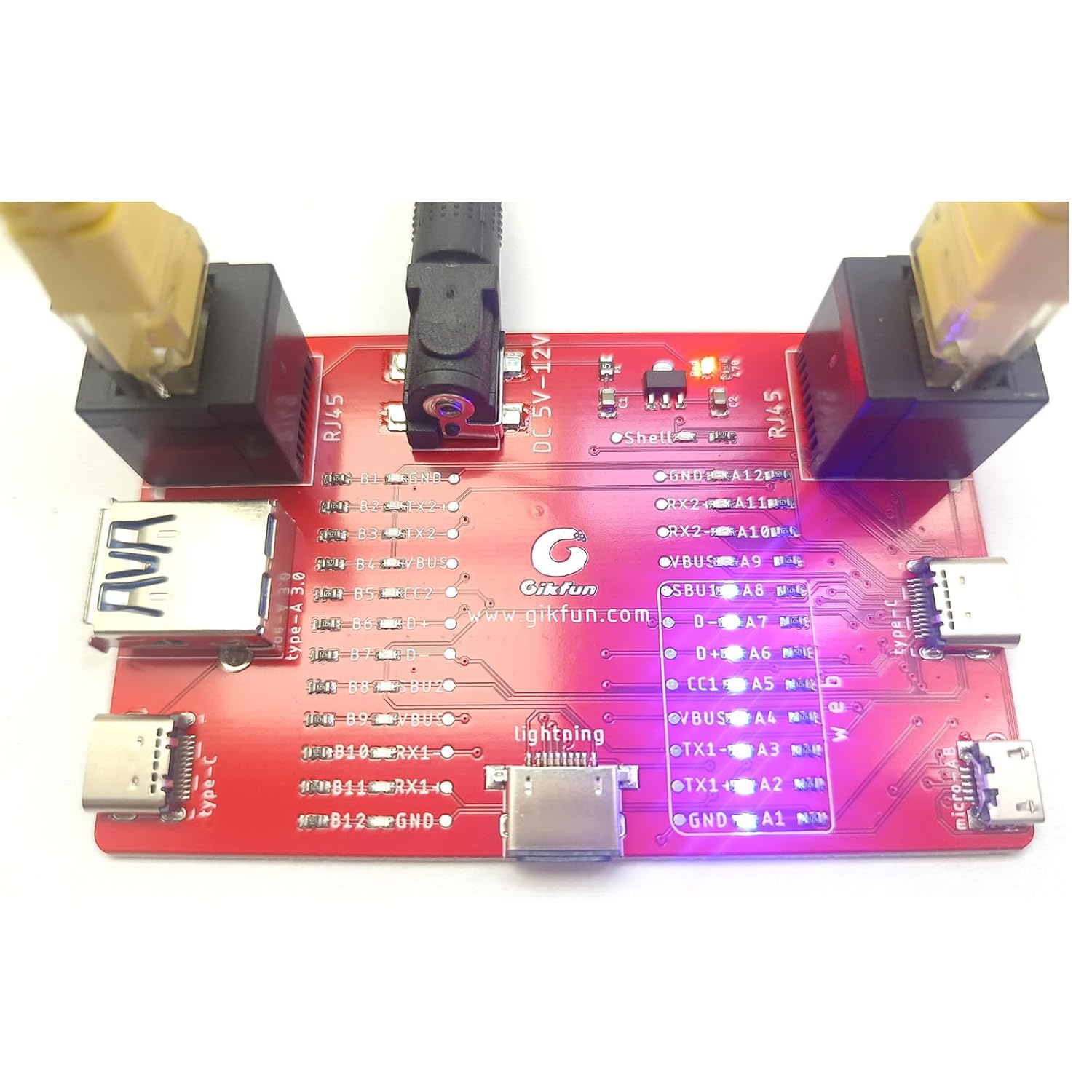
Figure 5.2: RJ45 network cable connected for testing.
5.3 LED Indicator Interpretation
The board features a detailed layout of pin labels next to each LED, corresponding to the various USB and RJ45 connections. Refer to the diagram below for a clear understanding of each indicator.

Figure 5.3: Labeled diagram of the Gikfun USB Cable Tester Board.
Each LED corresponds to a specific pin or wire within the cable. If an LED is lit, it indicates that the corresponding pin has continuity. If an LED remains off when it should be lit for a functional cable, it suggests a break or fault in that specific wire.
5.4 Vidjo ta' Dimostrazzjoni tal-Prodott
Video 5.4: Official demonstration of the Gikfun USB Cable Tester Board in use, showing various cable tests.
6. Manutenzjoni
To ensure the longevity and accurate performance of your Gikfun USB Cable Tester Board, follow these maintenance guidelines:
- Tindif: Use a soft, dry cloth to wipe the surface of the board. Avoid using abrasive cleaners or solvents that could damage the components or labels.
- Ħażna: Store the tester in a cool, dry place away from direct sunlight, excessive heat, and moisture.
- Immaniġġjar: Handle the board with care to avoid dropping it or subjecting it to strong impacts, which could damage the electronic components or connectors.
7 Issolvi l-problemi
7.1 No LEDs Light Up
- Iċċekkja l-Provvista tal-Enerġija: Ensure a DC 5V-12V power supply is correctly connected to the barrel jack. Verify the power supply is functional and providing the correct voltage.
- Konnessjoni tal-Cable: Confirm that the cable being tested is properly inserted into both the input and output ports on the tester.
7.2 Incorrect LED Readings
- Cable Orientation (USB-C): For USB-C cables, ensure the cable is inserted correctly. USB-C is reversible, but some internal connections might be sensitive to orientation on certain testers. Try flipping the cable.
- Cable Type Mismatch: Ensure you are interpreting the LEDs based on the correct cable type (e.g., a charge-only USB cable will not light up data line LEDs).
- Damaged Cable: If certain LEDs do not light up for a cable that should be fully functional, the cable itself may be damaged or faulty.
8. Speċifikazzjonijiet
| Attribut | Valur |
|---|---|
| Brand | Gikfun |
| Mudell | GK1030 |
| Input tal-Enerġija | DC 5V-12V (barrel jack) |
| Supported USB Types | USB Type-A, USB Type-C, Micro-AB, Lightning |
| Supported Network Cable | RJ45 (Cat5e/6/7) |
| Tip ta' Indikatur | 24 indikaturi LED |
| Dimensjonijiet | 3.78 x 2.72 x 1.26 pulzieri |
| Piż | 2.08 uqija |
| ASIN | B0F1D5NDCV |
| UPC | 739807423452 |
9. Garanzija u Appoġġ
For warranty information and technical support, please contact Gikfun directly through their official channels or the retailer from whom you purchased the product. You can visit the Gikfun Store on Amazon for more information: Gikfun Official Store.


