1. Introduzzjoni
This manual provides essential information for the installation, operation, and maintenance of the Cisco IE-3400-8T2S-E Catalyst IE3400 Rugged Series Network Essential Switch. This device is designed for industrial environments, offering robust network connectivity. Please read this manual thoroughly before operating the device.
2. Informazzjoni dwar is-Sigurtà
Osserva l-prekawzjonijiet ta' sigurtà li ġejjin biex tevita korrimenti u ħsara lit-tagħmir:
- Żgura ertjar xieraq tal-apparat.
- Skonnettja l-enerġija qabel ma twettaq xi proċeduri ta' manutenzjoni jew installazzjoni.
- Operate the switch within the specified environmental conditions (temperature, humidity).
- Persunal kwalifikat biss għandu jinstalla u jagħmel manutenzjoni fuq dan it-tagħmir.
- Evita li tesponi l-apparat għall-umdità jew temperaturi estremi.
3. Kontenut tal-Pakkett
Ivverifika li l-pakkett tiegħek fih l-oġġetti li ġejjin:
- Cisco IE-3400-8T2S-E Catalyst IE3400 Rugged Series Network Essential Switch
- Dokumentazzjoni (Gwida ta' Bidu Mgħaġġel, Informazzjoni dwar is-Sigurtà)
- Mounting hardware (if included with specific model variant)
- Power connector terminal blocks
Jekk xi oġġetti huma nieqsa jew bil-ħsara, ikkuntattja lill-fornitur tiegħek immedjatament.
4. Fiżiku Żejjedview
The following diagram illustrates the front panel components of the Cisco IE-3400-8T2S-E switch.
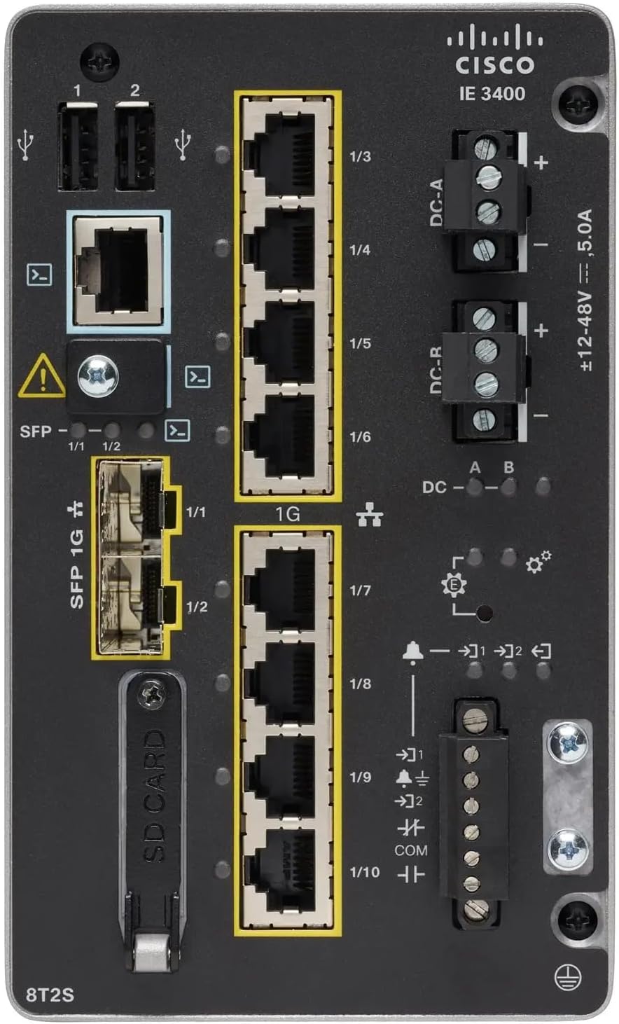
Figura 1: Front Panel Layout of the Cisco IE-3400-8T2S-E Switch
4.1. Front Panel Components Description
- USB Ports (1, 2): Two USB ports for connecting external devices or for configuration.
- Port tal-Console: An RJ45 console port for local management and initial configuration.
- SFP 1G Ports (1/1, 1/2): Two Small Form-Factor Pluggable (SFP) ports supporting 1 Gigabit Ethernet for fiber optic connections.
- 1G Ethernet Ports (1/3 - 1/10): Eight 1 Gigabit Ethernet RJ45 ports for standard network connections.
- DC Power Inputs (DC-A, DC-R): Redundant DC power input terminals, supporting a voltage range of ±12-48V at 5.0A.
- Invita tal-ert: Terminal for connecting the chassis to earth ground.
- Slot tal-Kard SD: Slot for an SD card, typically used for configuration backup or software storage.
- Alarm/Relay Ports (1/9, 1/10): Terminals for connecting external alarm systems or relay controls.
- Indikaturi LED: Various LEDs indicating power status (DC A/B), system status, link/activity for ports, and alarm status.
5. Setup
5.1. Immuntar tas-Swiċċ
The IE3400 series switches are designed for industrial environments and typically support DIN rail or wall mounting. Refer to the specific mounting instructions provided with your mounting kit for detailed steps.
5.2. Qawwa tal-Konnessjoni
- Ensure the power source is off before connecting.
- Connect the DC power cables to the DC-A and/or DC-R terminal blocks, observing polarity (+ and -). The switch supports redundant power inputs.
- Connect the grounding wire to the grounding screw on the front panel.
- Once all connections are secure, apply power to the switch. The DC-A and/or DC-B LEDs should illuminate.
5.3. Konnessjonijiet tan-Netwerk
- Portijiet Ethernet: Connect standard RJ45 Ethernet cables from your network devices to the 1G Ethernet ports (1/3 - 1/10).
- Portijiet SFP: Insert compatible SFP transceivers into the SFP 1G ports (1/1, 1/2) and connect fiber optic cables as required.
- Port tal-Console: For initial configuration, connect a console cable from your management workstation to the RJ45 console port.
6. Istruzzjonijiet Operattivi
6.1. L-Inizjali Tixgħel
Upon applying power, the switch will perform a power-on self-test (POST). The system LED will indicate the boot status. Once the boot process is complete, the switch will be ready for configuration.
6.2. Configuration Access
The switch can be configured via the console port using a terminal emulator or remotely via Telnet/SSH once an IP address is assigned. Refer to the Cisco IOS documentation for detailed configuration commands and procedures.
6.3. Indikaturi LED
Monitor the LED indicators on the front panel to understand the switch's operational status:
- DC-A/DC-B LEDs: Indicate the status of the primary and redundant DC power inputs.
- LED tas-sistema: Indicates the overall operational status of the switch (e.g., green for normal operation, amber for warning, red for fault).
- LEDs tal-Link/Attività (għal kull port): Indicate network link status and data activity on each Ethernet and SFP port.
- LED ta' allarm: Illuminates when a critical system alarm is triggered.
7. Manutenzjoni
7.1. Tindif
Periodically clean the exterior of the switch with a soft, dry cloth. Do not use liquid or aerosol cleaners. Ensure ventilation openings are free from dust and debris.
7.2. Aġġornamenti tal-Firmware
Iċċekkja regolarment l-appoġġ ta' Cisco website for the latest firmware updates. Applying updates can improve performance, add features, and address security vulnerabilities. Follow Cisco's official procedures for firmware upgrades.
7.3. Konsiderazzjonijiet Ambjentali
Ensure the switch operates within its specified temperature and humidity ranges. Proper airflow around the device is crucial for heat dissipation.
8 Issolvi l-problemi
Din it-taqsima tipprovdi passi bażiċi għas-soluzzjoni tal-problemi komuni.
8.1. Ebda Qawwa
- Verify that the power source is active and the power cables are securely connected to the DC-A/DC-R terminals.
- Check the DC-A/DC-B LEDs. If they are off, there is no power or a power supply issue.
8.2. No Network Link
- Ensure Ethernet or fiber optic cables are properly connected to both the switch port and the connected device.
- Check the Link/Activity LED for the specific port. If it is off, there is no link.
- Ivverifika li l-apparat konness huwa mixgħul u qed jaħdem sew.
8.3. System Alarm
- If the Alarm LED is illuminated, consult the Cisco IOS documentation for specific alarm codes and their meanings.
- Check system logs via the console or network management interface for detailed error messages.
9. Speċifikazzjonijiet
| Karatteristika | Speċifikazzjoni |
|---|---|
| Mudell | IE-3400-8T2S-E |
| Manifattur | Cisco |
| Portijiet Ethernet | 8 x 1 Gigabit RJ45 |
| Portijiet SFP | 2 x 1 Gigabit SFP |
| Tip ta' Interface | RJ45, SFP, PoE, PoE+ (model dependent) |
| Input tal-Enerġija | ±12-48V DC, 5.0A (Redundant) |
| Dimensjonijiet tal-Prodott | 36 x 9 x 55 ċm |
| Piż tal-oġġett | 2.28 Kilogrammi |
| Apparati Kompatibbli | Desktop, Laptop, Printer |
| UPC | 703670760433 |
10. Garanzija u Appoġġ
This product is offered as an Amazon Renewed item. Warranty and return policies are typically managed by the reseller (Amazon Renewed) for a specified period. Please refer to your purchase documentation or contact Amazon Renewed support for details regarding your specific warranty coverage.
For technical documentation, software downloads, and advanced support for the Cisco IE-3400-8T2S-E switch, please visit the official Cisco support website and search for your specific model.


