1. Introduzzjoni
The eletechsup R4IOJ32 is a 32-channel RS485 multi-function IO core board designed for industrial control applications. This compact board supports various input/output (IO) modes, including 32DI, 32DO, 16DI-16DO, 8DI-24DO, and 24DI-8DO, configurable via jumpers. It features Modbus RTU communication, making it suitable for PLC and HMI remote IO expansion. The board allows for flexible configuration of input and output levels (NPN/PNP) through register settings. Its small form factor and 2.54mm pin header interface facilitate easy integration into custom circuit boards and systems.
2. Informazzjoni dwar is-Sigurtà
- Tiżgura provvista ta 'enerġija xierqa voltage and polarity to prevent damage to the board.
- Avoid short circuits on any pins or terminals.
- Handle the board with care to prevent electrostatic discharge (ESD) damage.
- Disconnect power before making any connections or changes to the board.
- This device is intended for use by qualified personnel familiar with electronic components and Modbus communication protocols.
3. Prodott Aktarview
The R4IOJ32 board is available in two versions: 'Only Board' and 'With Pin'. The 'With Pin' version includes pre-soldered 2.54mm pin headers for easier breadboard or Dupont wire connections.

Figure 3.1: R4IOJ32 'Only Board' (left) and 'With Pin' (right) versions. The 'With Pin' version includes pre-soldered pin headers for convenience.
The board features clearly labeled pins for power, ground, RS485 communication, and 32 digital input/output channels. Mode selection jumpers and a reset jumper are also present.
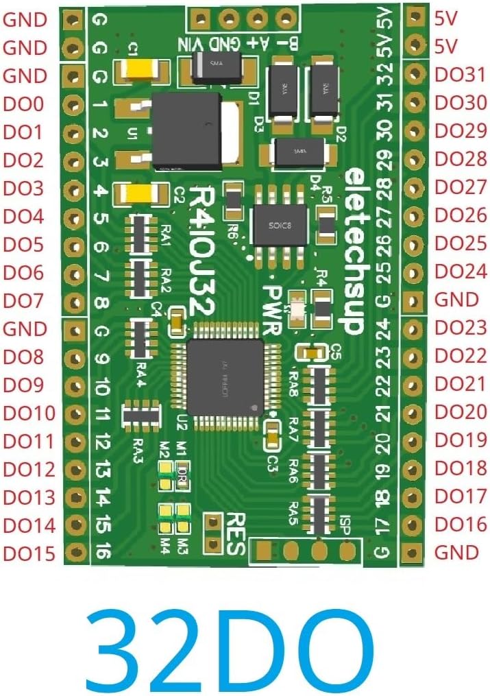
Figura 3.2: Fuq view of the R4IOJ32 board, illustrating the pinout for a 32 Digital Output (DO) configuration. Labels include GND, 5V, and DO0-DO31.
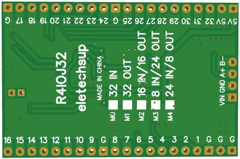
Figura 3.3: Qiegħ view of the R4IOJ32 board, highlighting the mode selection jumpers (M0-M4) used to configure the IO functionality.
4. Setup
4.1 Konnessjoni tal-Provvista tal-Enerġija
The R4IOJ32 board supports two power supply options. Only one power supply should be used at a time.
- Provvista tal-Enerġija 1: DC 6-26V (with anti-reverse connection protection). Connect to the 'VIN' and 'GND' terminals.
- Provvista tal-Enerġija 2: DC 4-5.5V (reverse connection prohibited). Connect to the '5V' and 'GND' terminals.

Figure 4.1: Power supply connection points and RS485 port on the R4IOJ32 board. Note the two distinct power input options.
4.2 Konnessjoni tal-Komunikazzjoni RS485
Connect the RS485 A and B lines from your master device (e.g., PLC, HMI) to the corresponding 'A' and 'B' terminals on the R4IOJ32 board. Ensure proper polarity for reliable communication.
4.3 IO Mode Selection
The R4IOJ32 board is a multi-function board, allowing you to select various IO modes (32DI, 32DO, 16DI-16DO, 8DI-24DO, 24DI-8DO) using jumpers M0-M4. These jumpers are typically 0603 0Ω resistors or wire links.

Figure 4.2: Jumper configuration table for selecting different IO function modes. The image shows the soldering patterns for M0-M4 to achieve 32DI, 32DO, 16DI-16DO, 8DI-24DO, and 24DI-8DO.
Refer to the table in Figure 4.2 to configure the desired IO mode by soldering or desoldering the appropriate jumpers (M0, M1, M2, M3, M4).
4.4 Input and Output Level Configuration (NPN/PNP)
The input and output levels (NPN/PNP) can be switched by modifying registers 0X00F5 and 0X00F6 via Modbus RTU commands. The default configuration is NPN input and NPN output.

Figure 4.3: Various input and output level configurations (NPN/PNP) and their corresponding register settings (0X00F5, 0X00F6). This diagram illustrates how to connect external signals for each type.
5. Istruzzjonijiet Operattivi
5.1 Komunikazzjoni Modbus RTU
The R4IOJ32 communicates using the Modbus RTU protocol over RS485. It supports the following function codes:
- Write Functions: 05 (Write Single Coil), 06 (Write Single Register), 15 (Write Multiple Coils), 16 (Write Multiple Registers)
- Read Functions: 01 (Read Coils), 02 (Read Discrete Inputs), 03 (Read Holding Registers)
The board supports various baud rates and parity settings:
- Rati ta' baud: 1200, 2400, 4800, 9600 (default), 19200, 38400, 57600, 115200 bps
- Parità: Xejn, Fard, Anki
In Modbus command mode, the R4IOJ32 can support up to 247 devices in parallel on the same RS485 bus.
5.2 Input Port Status
The status of the input ports can be queried by the master device (default mode) or configured for automatic reporting, depending on the specific firmware or register settings.
5.3 Abnormal Communication Settings
The board offers configurable behavior in case of abnormal communication:
- By setting register 0X00F3, the board can be configured to restart automatically when communication is abnormal.
- By setting register 0X00F4, all output ports can be configured to close (turn off) when communication is abnormal, providing a fail-safe mechanism.
6. Manutenzjoni
- Tindif: Żomm il-bord nadif u ħieles mit-trab u l-fdalijiet. Uża pinzell artab u niexef jew arja kkompressata għat-tindif. Evita li tuża likwidi jew solventi.
- Ambjent: Operate the board within its specified temperature and humidity ranges. Avoid exposure to extreme temperatures, moisture, or corrosive environments.
- Konnessjonijiet: Periodically check all wiring and connections to ensure they are secure and free from damage.
7 Issolvi l-problemi
7.1 Kwistjonijiet Komuni
- Ebda Qawwa: Check power supply connections and voltage. Ensure only one power supply is connected.
- Nuqqas ta' Komunikazzjoni: Verify RS485 A/B line polarity, baud rate, and parity settings. Check for bus termination if necessary. Ensure the Modbus master is correctly configured.
- Incorrect IO Behavior: Review the jumper settings for IO mode selection (Section 4.3). Check the NPN/PNP configuration via registers (Section 4.4).
7.2 Irrisettja l-Fabbrika
To restore the board to its factory default settings, short the 'RES' jumper for approximately 5 seconds. This will reset all configurable parameters to their initial values.
Figure 7.1: Location of the 'RES' jumper on the R4IOJ32 board, used for performing a factory reset.
8. Speċifikazzjonijiet
| Karatteristika | Speċifikazzjoni |
|---|---|
| Provvista tal-Enerġija 1 | DC 6-26V (with anti-reverse protection) |
| Provvista tal-Enerġija 2 | DC 4-5.5V (reverse connection prohibited) |
| Kurrent tax-Xogħol | 9mA |
| Protokoll ta' Komunikazzjoni | Modbus RTU |
| Kodiċi tal-Funzjoni Modbus | Write: 05, 06, 15, 16; Read: 01, 02, 03 |
| IO Modes (Selectable) | 32DI, 32DO, 16DI-16DO, 8DI-24DO, 24DI-8DO |
| Livelli ta' Input/Output | NPN/PNP (configurable via registers 0X00F5/0X00F6) |
| Mod ta 'Input | 3.3V/5V TTL level, low level (default)/high level input |
| Modalità tal-Ħruġ | 5V TTL level, low level (default)/high level output |
| Max Devices (Modbus) | 247 |
| Rati tal-Baud | 1200, 2400, 4800, 9600 (default), 19200, 38400, 57600, 115200 bps |
| Parità | Xejn, Fard, Anki |
| Interface | 2.54mm Pin Header |
| Dimensjonijiet | 51mm x 34mm x 4mm (L x W H x) |
| Piż | 8 gramma |
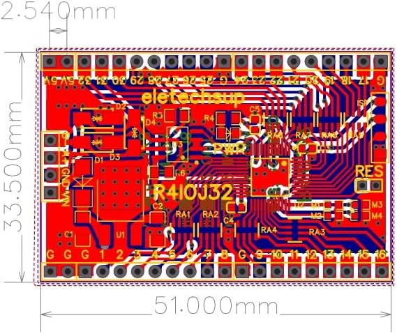
Figure 8.1: Dimensional drawing of the R4IOJ32 board, showing its compact size of 51.000mm by 33.500mm.

Figure 8.2: Detailed pinout diagrams for the R4IOJ32 board configured in 32DI, 32DO, 16DI-16DO, 8DI-24DO, and 24DI-8DO modes, illustrating the assignment of each pin.
9. Garanzija u Appoġġ
For detailed documentation, technical support, or warranty inquiries, please contact eletechsup customer service through the official channels where the product was purchased. Ensure to provide your product model (R4IOJ32) and any relevant purchase information for efficient assistance.