Prodott Overview
The MICTUNING P1s RGB 12 Gang Switch Panel is a high-power, multifunction toggle switch system designed for various 12V-24V DC applications, including trucks, RVs, off-road vehicles, and marine vessels. It features advanced controls for managing multiple accessories with customizable RGB backlighting and brightness levels.
Karatteristiċi Ewlenin
- MARKET-LEADING 3 SILICONE BUTTONS: MICTUNING RGB 5 Inch 12 Gang Switch Panel UPGRADED with 3 silicone button for more convenient and functionality operation, include ON/OFF switch with memory function, Brightness Adjustment Button, RGB Color Adjustment Button. The Silicone Button not only allows for blind operation, but also enhance hand feel
- ACC OR BATTERY WIRING WAY: RGB 12 Gang Switch Panel has 2 wiring methods for option: Connect ACC or Battery. The control box with push switch to freely switch ACC or battery power, simple easy and safe power connection. Toggle switch panel also offer 2 types of mounting: Vertical or Horizontal installation, you can install the control box and switch panel according to your needs
- 11 RGB COLORS MODES & 5-LEVEL BRIGHTNESS: Upgrade more backlit colors to match your vehicle and brighten your mood. Short press "RGB" button to switch 8 single color(red orange yellow green cyan blue purple white), and long press to switch between Gradient/ Jump/ Breathing. Also, there are 5-level brightness adjustment (100%, 75%, 50%, 25%, 10%), offer you most comfortable visual brightness while driving
- 5'' STURDY SWITCH PANEL MORE STABLE: The control panel increase 20% size, with large current and greater stability, safe to use. Rated at 12V/960W,24V/1920W, Maximum Current: 80A, Operating Temperature: - 40°C ~ + 85°C, IP65 waterproof rate. Aluminum alloy housing with sturdy iron bracket for long service time. Bonus 5 fuses included to well protect your car circuit
- NEAT AND CLEAR WIRING: Rocker switch with a Circuit Control Relay System, which help to clean up all wiring harness. Bonus 140pcs labeling stickers included for DIY your specific need. Suitable for RV, 12V-24V DC marine, car, truck, off-road, ATV/UTV, boat, yachts, Caravans, etc
- POSITIVE OUTPUT PANEL: This is a positive output switch panel that supports common cathodes, It means the negative wire can be connected to the negative terminal of control box, battery and car, which simplifies the wiring
X'hemm fil-Kaxxa
- 1x 12 Gang Switch Panel
- 1x Circuit Control Box
- 5x Parentesi tal-Immuntar
- 140x Switch Labels
- 1x 100A Circuit Breaker
- 7x Xedd tal-Wiring
- 8x Irbit tal-Cable
- Manwal ta' Istruzzjoni
- Viti
- 5x Fuses (2x 30A, 1x 20A, 1x 15A, 1x 10A)

Figure 1: Package Contents. The image displays all components included in the MICTUNING P1s RGB 12 Gang Switch Panel kit, neatly laid out.
Setup
1. Control Box Installation
The control box is the central unit for the switch panel. It can be mounted in various locations depending on your vehicle's layout.
- Select a suitable, secure location for the control box, preferably near the vehicle's battery.
- Use the provided mounting brackets and screws to firmly attach the control box. Ensure adequate ventilation and clearance from moving parts or heat sources.
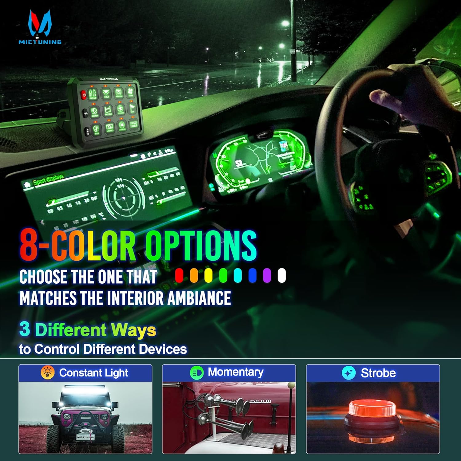
Figure 2: 2-Way Mounting Options. The diagram illustrates flexible installation methods for both the switch panel and the control box.
Video 1: How to Install P1s 12 Gang Switch Panel. This video provides a step-by-step guide on installing the control box and switch panel in a vehicle's engine bay.
2. Il-wajers tal-kaxxa tal-kontroll
The control box offers two primary wiring methods: ACC (Accessory) or direct Battery connection.
- Konnessjoni tal-Enerġija: Connect the main positive cable (red) from the 100A circuit breaker to the positive terminal of your vehicle's battery. Connect the other end of the circuit breaker to the main power input on the control box.
- Konnessjoni mal-art: Connect the main negative cable (black) from the control box to the negative terminal of your vehicle's battery or a suitable chassis ground point.
- ACC or Battery Power Selection: The control box features a push switch to select between ACC or direct Battery power. This allows you to choose if the switch panel powers on with the ignition or remains constantly powered.

Figure 3: ACC or Battery Wiring Diagram. This diagram illustrates the two power source options and their connections to the control box.
Video 2: P1s 12 Gang Switch Panel with Common Cathode Wiring. This video demonstrates the common cathode wiring method for simplified connections.
3. Switch Panel Mounting
The switch panel can be mounted vertically or horizontally in your vehicle's interior.
- Choose a convenient location for the switch panel, such as the dashboard, center console, or overhead.
- Attach the switch panel to your chosen surface using the appropriate mounting brackets and hardware.

Figure 4: Dashboard Mounting Example. The switch panel is shown installed on a vehicle's dashboard.
Istruzzjonijiet Operattivi
1. Funzjonijiet Bażiċi tal-Buttuni
- ON/OFF Switch (Power Button): Press to turn the entire switch panel on or off. It features a memory function, retaining the last state.
- Buttuna ta' Aġġustament tal-luminożità: Short press to cycle through 5 levels of brightness (100%, 75%, 50%, 25%, 10%) for the panel's backlight.
- RGB Color Adjustment Button: Short press to switch between 8 single RGB colors (Red, Orange, Yellow, Green, Cyan, Blue, Purple, White).
- RGB Mode Selection: Long press the RGB button to switch between Gradient, Jump, and Breathing backlight modes.
Video 3: How to Set RGB, Brightness and 3 Functions. This video demonstrates how to adjust the RGB colors, brightness levels, and switch between different lighting modes.
Video 4: Mictuning Upgrade P1s 12 Gang Switch Panel for Truck. This video highlights the upgraded features and functionality of the P1s 12 Gang Switch Panel.
2. Customizing Switch Functions (Momentary/Strobe)
Each switch can be configured for constant ON/OFF, momentary, or strobe functions.
- To enter setting mode for a specific switch, long press the corresponding switch button until its backlight flashes red.
- While in setting mode, short press the switch button to cycle through momentary (red flash) and strobe (blue flash) settings.
- Long press the switch button again to exit setting mode and save your selection.

Figure 5: Lighting Modes and Color Options. This image illustrates the various backlight colors and the three operational modes for connected devices.
Video 5: How to Install P1s 12 Gang Switch Panel. This video also demonstrates the momentary and strobe functions of the switches.
Manutenzjoni
Regular maintenance ensures optimal performance and longevity of your switch panel.
- Periodically inspect all wiring connections for tightness and signs of wear or corrosion.
- Keep the switch panel and control box clean and free of dust or debris. Use a soft, dry cloth for cleaning.
- Check the fuses regularly. If a connected accessory stops working, inspect its corresponding fuse in the control box. Replace blown fuses with ones of the correct amperage.
- Ensure the control box remains in a well-ventilated area to prevent overheating.
Issolvi l-problemi
- Il-Panel Mhux Mixgħul: Check the main power connections to the battery and the 100A circuit breaker. Ensure the circuit breaker is not tripped. Verify the ACC/Battery selection switch is in the correct position.
- Individual Accessory Not Working: Check the wiring connection for that specific accessory to the control box. Inspect the corresponding fuse in the control box and replace if blown.
- Kwistjonijiet tad-Dawl ta' Wara: If the backlight is not functioning correctly, ensure the panel is powered on. Try adjusting the brightness using the brightness adjustment button.
- Is-Swiċċ Mhux Jirrispondi: If a switch is unresponsive, try resetting the entire panel by turning it off and on. If the issue persists, check the wiring to that specific switch.
Speċifikazzjonijiet
| Speċifikazzjoni | Dettall |
|---|---|
| Mod ta' Operazzjoni | ON-OFF-ON |
| Klassifikazzjoni kurrenti | 60 Amps |
| Vol Operattivtage | 12-24 volt |
| Kurrent Massimu | 80A |
| Qawwa Massima | 12V/960W, 24V/1920W |
| Tip ta' Kuntatt | Normalment Miftuħ |
| Tip ta' Konnettur | Ipplaggja |
| Brand | MICTUNING |
| Terminal | Invita |
| Dimensjonijiet tal-oġġett (L x W x H) | 9.5 x 5.9 x 3.54 pulzieri |
| Tip ta 'Ċirkwit | 12-mod |
| Tip ta' Attwatur | Toggle |
| Klassifikazzjoni tal-Protezzjoni Internazzjonali | IP65 |
| Temperatura operattiva | -40°C ~ +85°C |
| Materjal | Aluminum Alloy Housing |
Garanzija u Appoġġ
MICTUNING stands behind its products with a commitment to customer satisfaction.
- Satisfaction Defender: Enjoy 30 days Money Back/Replacement.
- Garanzija: Worry-free 24-month Warranty.
- Appoġġ għall-Klijent: Within 4 Hours Friendly Response, Lifetime Customer Support.
- Pjanijiet ta' Protezzjoni: Additional protection plans are available for purchase (e.g., 3-Year Protection Plan, 4-Year Protection Plan, Complete Protect).
- Kuntatt: For support, log in to your Amazon account, go to "Your orders", find the order ID, and click "Contact seller".