1. Introduzzjoni
This manual provides detailed instructions for the installation, operation, and maintenance of the eletechsup 32-Channel PNP Optically Isolated Input Switching Digital Collector Board, an RS485 Modbus RTU Module. This module is designed for industrial automation applications requiring reliable digital signal acquisition and communication.
2. X'hemm fil-Kaxxa
- 1 x 32CH PNP Switching Signal Acquisition RS485 Input Board (Module)
Note: The specific configuration (with or without shell) depends on the purchased variant. This manual refers to the "no Shell" variant.
3. Karatteristiċi
- 32-Channel PNP Optically Isolated Input: Designed for robust digital signal acquisition.
- Wide Operating Voltage: Supports DC 6.5-25V (compatible with 9V, 12V, 24V systems).
- Low Working Current: Operates efficiently with 8-20mA current consumption.
- Komunikazzjoni RS485: Features 3000VDC photoelectric isolation for reliable data transmission.
- Digital Input Isolation: Provides 5000VDC photoelectric isolation for digital inputs, enhancing safety and noise immunity.
- PNP Switch/Digital Input Level Compatibility: Supports 3.3V, 5V, 12V, and 24V input levels.
- MODBUS RTU Support: Utilizes Function Codes 02, 03, 06, and 16 for versatile communication.
- Configurable Baud Rates: Supports 1200-115200 baud rates with None/Even/Odd parity options.
4. Speċifikazzjonijiet
| Parametru | Valur |
|---|---|
| Isem tal-Prodott | 32CH PNP Optically Isolated Input Switching Digital Collector Board RS485 Modbus RTU Module |
| Numru tal-Mudell | 24DIB32_PNP |
| Ħidma Voltage | DC 6.5-25V (9V, 12V, 24V compatible) |
| Kurrent tax-Xogħol | 8-20mA |
| RS485 Isolation | 3000VDC Photoelectric Isolation |
| Digital Input Isolation | 5000VDC Photoelectric Isolation |
| PNP Switch/Digital Input Level | 3.3V, 5V, 12V, 24V |
| MODBUS RTU Function Codes | 02, 03, 06, 16 |
| Rati tal-Baud | 1200-115200 bps |
| Parity Options | Xejn, Anke, Fard |
| Dimensions (Only Board) | 120 x 72 x 25 mm |
| Weight (Only Board) | 114 gramma |
5. Setup u Wiring
Proper setup and wiring are crucial for the correct operation of the module. Follow the diagrams and instructions below carefully.
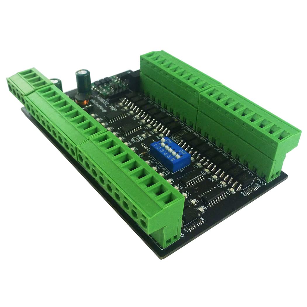
Figura 5.0: Aktarview of the eletechsup 32CH PNP Digital Input Module. This image shows the overall layout of the module board with its 32 channels and communication interfaces.

Figure 5.1: Wiring Diagram for 3-30V PNP Digital Signal Input. This diagram illustrates how to connect 3-30V PNP digital signals to the input terminals and the DC 6.5-25V power supply, along with RS485 connections.
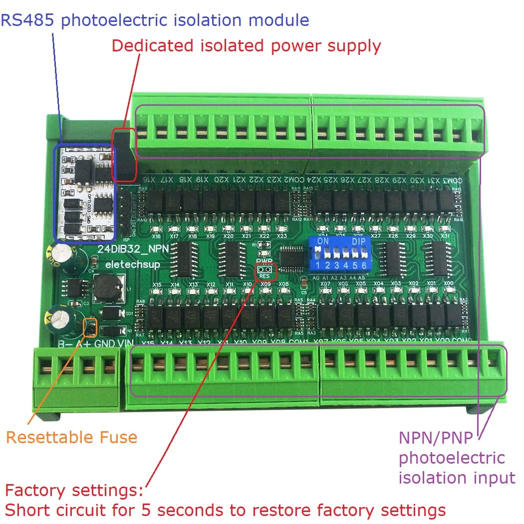
Figure 5.2: Key Components and Features. This image highlights the RS485 photoelectric isolation module, dedicated isolated power supply, resettable fuse, and NPN/PNP photoelectric isolation input sections of the board.
5.1 Konnessjoni tal-Provvista tal-Enerġija
- Connect a DC power supply within the range of 6.5V to 25V to the VIN and GND terminals. Ensure correct polarity.
5.2 Digital Input Connections (PNP)
- Connect your PNP digital signals (3.3V, 5V, 12V, or 24V) to the corresponding input channels (X00-X31).
- Ensure the common ground for the input signals is correctly connected.
5.3 Konnessjoni tal-Komunikazzjoni RS485
- Connect the RS485 A+ and B- terminals to your RS485 network.
- Observe proper polarity for A+ and B- connections to avoid communication issues.
6. Istruzzjonijiet Operattivi
The module communicates using the Modbus RTU protocol over an RS485 interface. This section outlines the basic operation and Modbus register access.
6.1 Komunikazzjoni Modbus RTU
- The module acts as a Modbus RTU slave device.
- Supported Function Codes: 02 (Read Input Status), 03 (Read Holding Registers), 06 (Write Single Register), 16 (Write Multiple Registers).
- Baud rates can be configured from 1200 to 115200 bps. Parity options include None, Even, and Odd.
6.2 Reading Digital Inputs
Digital input states can be read using Modbus Function Code 02 (Read Input Status) or by accessing specific holding registers (Function Code 03).
Video 6.1: Demonstrating Digital Input Reading via Modbus RTU. This video shows the process of reading digital input states from the module using Modbus polling software, illustrating how input changes are reflected in the software interface.
The video demonstrates how to configure a Modbus client to read the input registers. When a digital input is activated, the corresponding register value changes, indicating the input status.
6.3 Modbus Register Map (Example)
Refer to the specific Modbus RTU protocol documentation for the full register map. Below is an example of how input registers might be structured:
| Indirizz tar-Reġistru | Irreġistra l-Kontenut | Valur | Rimarki |
|---|---|---|---|
| 0x0000-0x00AF (0-175) | DI digital input (Coil) | 0x0000: No input 0x0001: Has input | R |
| 0x00C0-0x00C2 (192-194) | DI digital input (Register) | 0x00C0: 0-15 Channels 0x00C1: 16-31 Channels 0x00C2: 32-47 Channels | R |
Note: The exact register map may vary. Always refer to the latest official documentation provided by the manufacturer for precise details.
7. Applikazzjonijiet
The eletechsup 32CH PNP Digital Input Module is suitable for a wide range of industrial and home automation applications, including:
- Automated Industry PLC systems
- PLC IO expansion boards
- Digital input to RS485 conversion
- Smart Home and Home Automation systems
- Identification systems
- CCTV Camera PTZ Control
- Sistemi ta' sigurtà
- General RS485 remote control applications
8 Issolvi l-problemi
Jekk tiltaqa' ma' problemi bil-modulu tiegħek, ikkunsidra l-passi li ġejjin għas-soluzzjoni tal-problemi:
- Ebda Qawwa: Verify that the DC power supply is connected correctly (6.5-25V) and providing power. Check for any blown fuses (the module has a resettable fuse).
- Żbalji ta' Komunikazzjoni:
- Ensure RS485 A+ and B- connections are not reversed.
- Confirm that the baud rate, parity, and stop bits settings on your Modbus master match the module's configuration.
- Check the Modbus slave ID.
- Verify cable integrity and termination resistors if applicable for long distances.
- Incorrect Input Readings:
- Confirm that the digital input signals are within the supported voltage range (3.3V, 5V, 12V, 24V).
- Ensure proper common ground connections for input signals.
- Check the Modbus register addresses being read.
- Modulu Mhux Risponsiv: If the module becomes unresponsive, try power cycling it. If issues persist, a factory reset might be necessary (refer to advanced documentation for specific procedures, often involving short-circuiting a specific pin for a duration).
9. Manutenzjoni
The eletechsup 32CH PNP Digital Input Module is designed for reliable operation with minimal maintenance. However, adhering to the following guidelines can help ensure its longevity:
- Kundizzjonijiet Ambjentali: Operate the module within its specified temperature and humidity ranges. Avoid exposure to excessive dust, moisture, or corrosive environments.
- Tindif: If cleaning is necessary, disconnect power and use a soft, dry cloth. Do not use liquid cleaners or solvents.
- Konnessjonijiet: Iċċekkja l-konnessjonijiet tal-wajers kollha perjodikament biex tiżgura li huma sikuri u ħielsa mill-korrużjoni.
- Aġġornamenti tal-Firmware: Iċċekkja l-manifattur website for any available firmware updates that may improve performance or address known issues. Follow update instructions carefully.