1. Introduzzjoni
This instruction manual provides detailed guidance for assembling and operating your ICStation Line Following Tracking Smart Car (Stepper Motor) Kit. This educational kit is designed to enhance intellectual development, hands-on ability, and understanding of basic electronics and robotics principles. It is suitable for students and beginners interested in STEM learning and soldering practice.
The smart tracking car operates based on the principle of light reflectivity difference. A photoresistance sensor on the board detects red LED light reflected from the ground to determine if it is following a black line.
2. Informazzjoni dwar is-Sigurtà
Please read all instructions carefully before beginning assembly. This kit involves soldering, which requires caution. Always work in a well-ventilated area and wear appropriate safety gear, such as safety glasses. Keep small components away from young children to prevent choking hazards. Adult supervision is recommended for users under 13 years of age.
3. Kontenut tal-Pakkett
Iċċekkja li l-komponenti kollha elenkati hawn taħt huma preżenti fil-kit tiegħek:
- Bord taċ-ċirkwit stampat (PCB)
- Reżisturi tal-film tal-metall
- DIP-8P IC socket
- Self-Locking switch
- Potenzjometri
- S8550 transistors
- Kondensers
- LEDs ħomor
- LEDs bojod
- Mecanum wheels
- Caster support bolts and nuts
- Fotoreżisturi
- Battery case (for 2 AA batteries, batteries not included)
- Gaskits
- Steel shafts
- Three-way sleeves
- Gerijiet
- Muturi
- LM393 IC
- Diversi viti u qfieli

Figura 3.1: Il-komponenti kollha inklużi fil-kit.

Figura 3.2: Dettaljat view of the PCB with component placement labels.
4. Istruzzjonijiet tal-Assemblea
4.1. Circuit Installation
- Install metal film resistors, DIP-8P IC socket, Self-Locking switch, Potentiometer, S8550, Capacitors, and Red LEDs onto the PCB according to the markings on the board.
- Install Mecanum wheels. Insert the support bolts of the caster into the hole, tighten the nuts screwed into the caster, and finally fit the caster and tighten.
- Install photoresistors and white LEDs on the reverse side of the PCB.
- Install the battery case.
- Ittestjar Inizjali: Install two AA batteries (not included). Press the switch. If both white LEDs turn ON, the circuit installation is successful. If the LEDs remain off, please recheck all soldering connections.
4.2. Mechanical Parts Installation
- Install the four gaskets onto the circuit board.
- Insert a steel shaft through the center hole of each wheel. Ensure the direction is inserted from the side with the raised sleeve of the wheel. It is best to insert the steel shaft parallel to the smooth side of the wheel.
- Place a three-way sleeve onto the steel shaft, close to the wheel, followed by a gasket onto the steel shaft, close to the three-way sleeve. Ensure they are installed in place and the three-way sleeve can toggle flexibly.
- Place a gear onto the steel shaft in the center.
- Put a three-axis sleeve onto the end of the steel shaft to complete the wheel assembly for the car side.
- Install the motors.
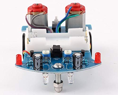
Figura 4.1: Close-up view of the assembled circuit board and components.
5. Istruzzjonijiet Operattivi
Once assembled, the smart car is ready for operation. You can design an interesting and winding route using a 1.5-2.0 cm wide black electrical tape on a flat surface. The car will then follow this black line.

Figure 5.1: Multiple assembled smart cars.
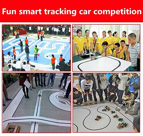
Figura 5.2: Eżample of smart cars following a black line in a competition setting.
5.1. Vidjo ta' Dimostrazzjoni
Video 5.1: A demonstration of the robot car following a line. This video shows the car in action on a black line track, demonstrating its line-following capabilities.
6. Manutenzjoni
To ensure the longevity and optimal performance of your smart car kit, keep it clean and free from dust and debris. Store components in a dry environment. Regularly check soldered connections for integrity. If the car's performance degrades, ensure the batteries are fresh and connections are secure.
7 Issolvi l-problemi
7.1. Kwistjonijiet Komuni u Soluzzjonijiet
- Car does not move after power on:
- Check the S8550 transistors.
- Check the 10-ohm resistors.
- Kun żgur li l-batteriji huma installati u ċċarġjati b'mod korrett.
- Verify all soldered connections are solid and there are no short circuits.
- Car does not follow the line correctly:
- Ensure the photoresistors and white LEDs are installed correctly on the reverse side of the PCB.
- Verify the LM393 IC is installed with the correct orientation.
- Check the black line's width (recommended 1.5-2.0 cm) and contrast against the surface.
- Ensure the environment has adequate lighting, but avoid direct strong light that might interfere with the sensors.
- Operazzjoni intermittenti:
- Check for loose wires or components.
- Ensure the battery case connections are secure.
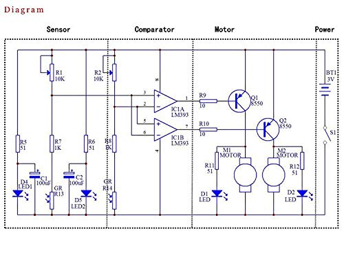
Figure 7.1: Circuit diagram for reference during troubleshooting.
8. Speċifikazzjonijiet
| Karatteristika | Dettall |
|---|---|
| Dimensjonijiet tal-Prodott | 4.5 x 3.4 x 0.4 pulzieri |
| Piż tal-oġġett | 12.35 uqija |
| Età Rakkomandata | 13 snin 'il fuq |
| Manifattur | Stazzjon tal-ICS |
| ASIN | B07P57N347 |
| Sors tal-Enerġija | 2 x Batteriji AA (mhux inklużi) |
9. Garanzija u Appoġġ
For any questions, technical assistance, or support regarding your ICStation product, please contact the manufacturer directly. ICStation is committed to providing professional help and support for product-related issues. Please refer to the product's original packaging or the seller's information on the purchase platform for specific warranty details and contact information.
You can also visit the official ICStation store for more information: ICStation Store on Amazon.

Figure 9.1: ICStation Brand Logo.


