1. Introduzzjoni
This manual provides comprehensive instructions for the uxcell DC 24V 530RPM Gear Motor with Encoder. This motor is engineered for applications requiring precise speed control and positional feedback, making it suitable for robotics, remote-controlled models, and various do-it-yourself (DIY) engineering projects. Please read this manual thoroughly before installation and operation to ensure safe and efficient use.
2. Informazzjoni dwar is-Sigurtà
- Dejjem skonnettja l-enerġija qabel ma twettaq kwalunkwe installazzjoni, wajers, jew proċeduri ta' manutenzjoni.
- Żgura li l-voltage and current are within the specified operating range (6-24V DC) to prevent damage to the motor or connected components.
- Avoid exposing the motor to excessive moisture, dust, or extreme temperatures.
- Do not attempt to disassemble the motor or gearbox beyond what is explicitly described in this manual. Unauthorized modifications can void the warranty and lead to malfunction.
- Handle the motor and its components with care to prevent physical damage.
3. Prodott Aktarview
The uxcell Gear Motor with Encoder integrates a DC motor, a reduction gearbox, and an optical encoder into a single unit. This combination allows for both powerful torque delivery and precise feedback on the motor's rotational position and speed. The robust metal construction ensures durability, while the D-shaped output shaft provides a secure connection for various mechanical components.

Figura 1: Quddiem view of the uxcell DC Gear Motor with Encoder.

Figura 2: Wara view of the motor, highlighting the integrated encoder module.
4. Speċifikazzjonijiet
Detailed technical specifications for the uxcell DC 24V 530RPM Gear Motor with Encoder are provided below:
| Parametru | Valur |
|---|---|
| Materjal | Metall |
| Kulur | Fidda |
| Vol ikklassifikattage | 24V DC |
| Voltage Firxa | 6-24V DC |
| Veloċità mingħajr tagħbija | 530 RPM |
| Veloċità tat-Tagħbija | 430 RPM |
| Kurrent bla tagħbija | 90mA |
| Kurrent tat-Tagħbija | 480mA |
| Stall Kurrenti | 2.5A |
| Torque | 3.2 kg.ċm |
| Proporzjon ta' Tnaqqis | 18.8:1 |
| Gearbox Size (D x L) | 37 x 22 mm (1.46 x 0.87 pulzier) |
| Motor Size (D x L) | 34.5 x 30 mm (1.36 x 1.18 pulzier) |
| Shaft Size (D x L) | 6 x 15.5 mm (0.24 x 0.61 pulzier) |
| Tul tal-Kejbil tal-Enkoder | 20 ċm (7.87-il pulzier) |
| Piż Gross | Appross. 190g |

Figure 3: Dimensional drawing of the gear motor, showing key measurements.
5. Setup u Installazzjoni
5.1 Immuntar tal-Mutur
The motor's face plate is equipped with six M3 threaded mounting holes. These holes are evenly spaced around the outer edge, forming a regular hexagon, with the centers of neighboring holes 15.5 mm apart. Use appropriate M3 screws to securely fasten the motor to your application's chassis or mounting bracket.

Figure 4: Detail of the motor's face plate with M3 mounting holes.
5.2 Wiring the Motor and Encoder
The encoder features six color-coded leads, terminated by a 6-pin female header with a 0.1-inch pitch. Connect these leads to your control system according to the pinout diagram below. Ensure correct polarity for both motor power and encoder signals.

Figure 5: Encoder wiring diagram with color-coded leads and pin functions.
- Hall Sensor B Vout: Encoder output B (square wave)
- Hall Sensor A Vout: Encoder output A (square wave)
- Hall Sensor Vcc: Encoder power supply (typically 5V, check your encoder's specific voltagrekwiżit e)
- Hall Sensor GND: Encoder ground
- Motor+: Positive terminal for motor power
- Motor-: Negative terminal for motor power
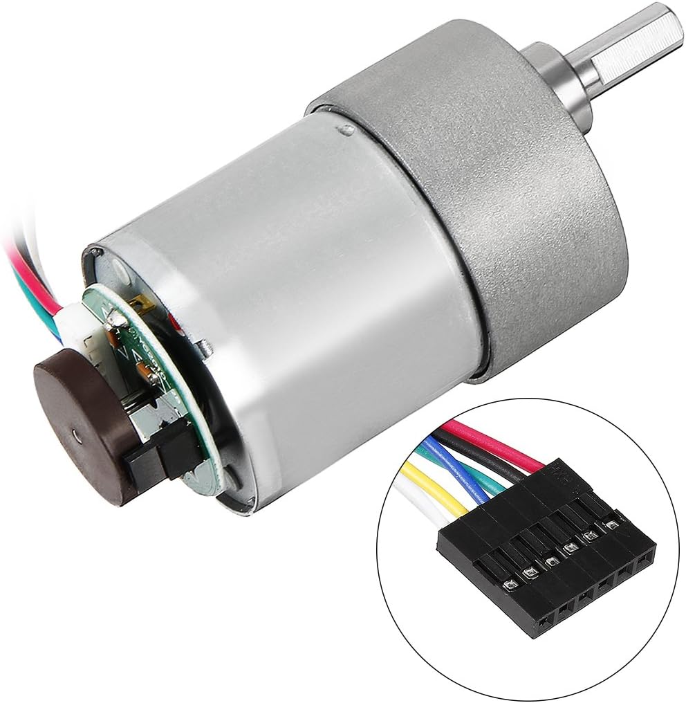
Figure 6: Encoder module with its attached 6-pin connector.
6. Istruzzjonijiet Operattivi
6.1 Powering the Motor
Connect a DC power supply within the 6-24V range to the motor's positive (Motor+) and negative (Motor-) terminals. Applying voltage will cause the motor to rotate. Reversing the polarity will reverse the direction of rotation.
6.2 Kontroll tal-Veloċità
The motor's speed can be controlled by varying the input voltage within its specified operating range. Alternatively, Pulse Width Modulation (PWM) can be used to achieve precise speed control, especially with microcontrollers.
6.3 Encoder Feedback
The integrated Hall sensor encoder provides two square wave outputs, A and B, which are approximately 90 degrees out of phase. These quadrature signals are crucial for determining:
- Rotational Direction: By observing the phase relationship between signals A and B.
- Veloċità Rotazzjoni: By counting the pulses over a given time interval.
- Positional Feedback: By tracking the total number of pulses from a known starting point.
Connect the encoder outputs to a microcontroller or dedicated encoder interface for processing these signals.
7. Manutenzjoni
- Keep the motor and gearbox clean and free from dust, debris, and foreign objects.
- Regularly inspect all wiring connections for signs of wear, fraying, or damage. Replace any damaged wires immediately.
- Avoid continuously operating the motor beyond its specified torque and current limits to prevent overheating and premature wear.
- Ensure proper ventilation around the motor, especially during prolonged operation, to dissipate heat effectively.
8 Issolvi l-problemi
8.1 Motor Not Running
- Iċċekkja l-Provvista tal-Enerġija: Ivverifika li l-provvista tal-enerġija hija konnessa b'mod korrett u li tipprovdi l-volum speċifikattage (6-24V DC).
- Iċċekkja l-Wiring: Ensure all motor power wires are securely connected and free from breaks or short circuits.
- Check Load: Confirm that the motor is not overloaded beyond its stall torque. Reduce the load if necessary.
8.2 Incorrect Speed or Erratic Operation
- Ivverifika Voltage: Tiżgura l-input voltage is stable and within the operating range.
- Inspect Load: Excessive or fluctuating load can affect motor speed.
- Iċċekkja għal Ostruzzjonijiet: Ensure the shaft and gearbox are free from any physical obstructions.
8.3 No Encoder Feedback
- Check Encoder Wiring: Verify that the encoder's Vcc, GND, and signal lines (A, B) are correctly connected to your control system.
- Check Encoder Power: Ensure the encoder is receiving appropriate power (typically 5V).
- Konfigurazzjoni tas-Softwer: Confirm that your microcontroller or control system is correctly configured to read and interpret the encoder signals.
9. Garanzija u Appoġġ
For specific warranty information, technical assistance, or customer support regarding your uxcell DC 24V 530RPM Gear Motor with Encoder, please refer to your purchase documentation or contact uxcell customer service directly. Keep your proof of purchase for any warranty claims.
