1. Introduzzjoni
This manual provides instructions for the safe and efficient operation of the AUTONICS TC4M-14R Temperature Controller. The TC4M-14R is a W72 x H72 single display 4-digit PID temperature controller with relay and SSR output, and one alarm output, designed for 100-240 VAC power supply. Please read this manual thoroughly before installation and operation to ensure proper use and prevent accidents.
2. Prekawzjonijiet tas-Sigurtà
- Tiżgura l-provvista tal-enerġija voltage is within the specified range (100-240 VAC). Incorrect voltage can cause damage or malfunction.
- Do not use the unit in environments with flammable or explosive gases, as this may lead to fire or explosion.
- Avoid installing the unit in areas subject to direct sunlight, excessive vibration, high humidity, or extreme temperatures outside the operating range.
- Always disconnect power before performing any wiring, maintenance, or inspection to prevent electric shock.
- This unit is designed for industrial control applications and is not intended as a safety device. For applications requiring safety, implement separate safety measures.
- Do not disassemble or modify the unit. Unauthorized modifications may void the warranty and pose safety risks.
3. Prodott Aktarview
The AUTONICS TC4M-14R is a compact and precise temperature controller. It features a clear 4-digit LCD display for accurate monitoring of both the process value (PV) and set value (SV). Utilizing advanced PID control algorithms, it ensures stable and accurate temperature regulation. The controller offers versatile output options, including both relay and Solid State Relay (SSR) outputs, making it suitable for various heating and cooling applications. Additionally, it includes one alarm output for critical process alerts.
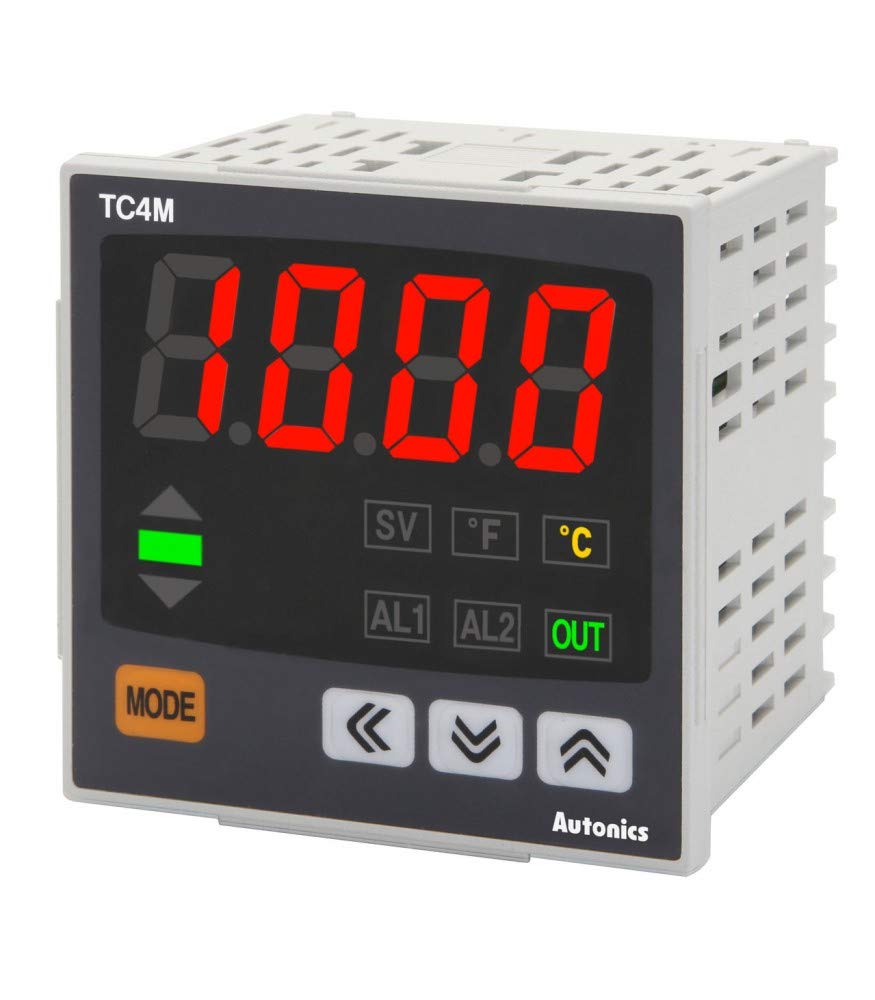
Figure 3.1: Front Panel of TC4M-14R. This image displays the controller's front face, highlighting the digital display, control buttons (Mode, Up, Down, Left/Right arrows), and indicator lights for SV, F, C, AL1, AL2, and OUT.
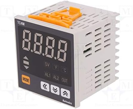
Figura 3.2: Ġenb View with Mounting Clips. This image shows the side profile of the TC4M-14R, including the orange mounting clips used for secure panel installation.
4. Setup u Installazzjoni
4.1 Immuntar
The TC4M-14R is designed for panel mounting. To install, cut a panel opening with dimensions of 68 mm x 68 mm. Insert the unit into the prepared opening from the front. Secure the controller firmly in place using the provided mounting brackets, attaching them from the rear of the panel.
4.2 Wajers
Importanti: Always ensure power is disconnected from the main supply before commencing any wiring procedures to prevent electric shock or damage to the unit.
- Input ta' Enerġija: Connect the 100-240 VAC power supply to the designated power terminals. Refer to the unit's label for exact terminal numbers.
- Input tas-Sensor: Connect your temperature sensor (e.g., K-type thermocouple, Pt100 RTD) to the sensor input terminals. Ensure correct polarity for thermocouples. The sensor type must be configured in the unit's parameters.
- Control Output (Relay & SSR): Connect your heating or cooling load to the relay output terminals and/or the SSR drive input to the SSR output terminals. The TC4M-14R provides both types of outputs.
- Riżultat ta 'allarm Connect any external alarm device (e.g., buzzer, indicator light) to the alarm output terminals.
Refer to the detailed wiring diagram printed on the side of the unit or in the full product manual for precise terminal assignments and connection guidelines.
5. Istruzzjonijiet Operattivi
5.1 Mixgħul
After completing all wiring and mounting, apply power to the unit. The controller will perform a brief self-test, and then the display will show the current process value (PV) and the set value (SV).
5.2 Issettjar tal-Valur Issettjat (SV)
- Agħfas il- MODALITÀ button briefly. The SV display will begin to flash, indicating it is ready for adjustment.
- Uża l- ↑ (Fuq) u ↓ (Down) arrow buttons to increase or decrease the SV.
- For faster adjustment, use the ← (Xellug) u → (Right) arrow buttons to move the cursor to different digits.
- Agħfas il- MODALITÀ Agħfas il-buttuna mill-ġdid biex tikkonferma l-SV il-ġdid u terġa' lura għall-operazzjoni normali.
5.3 Parameter Settings (PID, Alarm, etc.)
To access advanced parameters such as PID constants, alarm types, input sensor type, and other configuration settings, press and hold the MODALITÀ button for approximately 3 seconds. Use the arrow buttons to navigate through the parameter menu and adjust values as needed. A detailed explanation of each parameter can be found in the comprehensive product manual.
5.4 Output Indicators
- BARRA indicator: This green indicator illuminates when the main control output (Relay or SSR) is active, signaling that power is being supplied to the load.
- AL1 indicator: This red indicator illuminates when the condition for Alarm 1 is met, as configured in the parameter settings.
- AL2 indicator: This red indicator illuminates when the condition for Alarm 2 is met, if Alarm 2 is configured and enabled.
6. Manutenzjoni
6.1 Tindif
Wipe the unit's display and casing with a soft, dry cloth. For stubborn dirt, a slightly damp cloth may be used, followed by a dry cloth. Do not use abrasive cleaners, solvents, or alcohol-based solutions, as these can damage the plastic components and display.
6.2 Spezzjoni
Periodically inspect all wiring connections to ensure they are secure and free from corrosion or damage. Check that the unit is free from excessive dust accumulation, especially around any ventilation slots, to prevent overheating. Ensure the mounting is still firm.
6.3 Kalibrazzjoni tas-Sensor
If temperature readings appear inaccurate, first check the sensor connection for any faults. If the issue persists, consider recalibrating the sensor or replacing it if it is determined to be faulty. Refer to the full product manual for detailed sensor calibration procedures and troubleshooting steps.
7 Issolvi l-problemi
| Problema | Kawża Possibbli | Soluzzjoni |
|---|---|---|
| No display / Unit is off | L-ebda provvista tal-enerġija jew wajers mhux korretti. | Check power connections (100-240 VAC) and ensure power is supplied to the unit. Verify wiring against the diagram. |
| Temperature reading inaccurate or 'HHHH' / 'LLLL' displayed | Faulty sensor, incorrect sensor type setting, or poor sensor connection. | Verify the input sensor type setting matches the connected sensor. Check sensor wiring for breaks or short circuits. Replace sensor if necessary. |
| Control output not activating | Incorrect SV setting, PID parameters, or faulty output wiring/device. | Check the Set Value (SV). Review PID parameters (P, I, D, control mode). Inspect output wiring and the connected load (heater/cooler) for functionality. |
| L-allarm mhux qed jattiva | Incorrect alarm settings (type, setpoint) or faulty alarm output. | Verify alarm type and setpoint in the parameter settings. Check alarm output wiring and the connected alarm device. |
| Unit is unstable or overshoots | PID parameters are not optimally tuned for the process. | Perform auto-tuning or manually adjust PID parameters. Refer to the full manual for PID tuning instructions. |
8. Speċifikazzjonijiet
- Mudell: TC4M-14R
- Ditta: AWTONIĊI
- Metodu ta' Kontroll: PID Control (Auto-tuning function included)
- Tip ta' wiri: Single Display 4 Digit LCD
- Input: Universal Input (Supports various Thermocouple and RTD types, configurable)
- Output: Relay Output (1 contact), SSR Drive Output (1 output)
- Riżultat ta 'allarm 1 Alarm Output (Relay contact)
- Provvista tal-Enerġija: 100-240 VAC, 50/60 Hz
- Konsum tal-Enerġija: Max. 5 VA
- Dimensjonijiet: W72 x H72 x L70 mm (excluding terminals)
- Temperatura operattiva: 0 to 60 ℃ (32 to 140 ℉)
- Umdità Operattiva: 35 sa 85% RH (mingħajr kondensazzjoni)
- Immuntar: Immonta fuq il-Panew
9. Garanzija u Appoġġ
AUTONICS products are typically covered by a limited warranty against defects in materials and workmanship. The duration and terms of the warranty may vary by region and product. For specific warranty details, technical support, troubleshooting assistance, or service, please contact your local authorized AUTONICS distributor or visit the official AUTONICS website. When contacting support, please have your product model number (TC4M-14R) and purchase information readily available.


