1. Introduction to the Wiring Diagram
This document serves as a guide for effectively using the 1979 Ford Bronco Foldout Wiring Diagram. The diagram provides a comprehensive visual representation of the electrical circuits within your 1979 Ford Bronco vehicle. Its primary purpose is to assist in the identification, diagnosis, and repair of electrical system components and wiring paths. Familiarity with this diagram is crucial for anyone performing electrical work on the vehicle.
2. Understanding Diagram Symbols and Conventions
To accurately interpret the wiring diagram, it is essential to understand the symbols and conventions used. The diagram employs standardized electrical symbols to represent components such as switches, relays, fuses, motors, lights, and sensors. Wires are typically color-coded and may include numerical or alphabetical identifiers to denote their function or circuit. Wire thickness, often indicated by gauge numbers, signifies current carrying capacity.
Connections between wires are shown as dots or junctions, while wires crossing without a connection are typically depicted with an arc or simply crossing without a dot. Ground points are indicated by a specific ground symbol. Always refer to the legend or key provided within the diagram itself for specific symbol definitions and color codes relevant to the 1979 Ford Bronco.
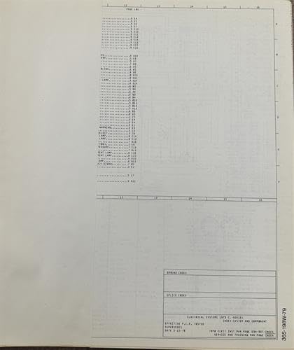
Figura 1: Eżample section of the 1979 Ford Bronco Foldout Wiring Diagram, illustrating circuit paths and component symbols.
3. Tracing Electrical Circuits
Tracing a circuit involves following the path of electricity from its power source, through various components, and back to ground. This process is fundamental for diagnosing electrical issues.
- Identifika l-Komponent: Locate the specific component (e.g., headlight, fuel pump, ignition switch) on the diagram that you wish to investigate.
- Sib is-Sors tal-Enerġija: Trace the wires leading to the component back towards the battery, often passing through fuses, relays, and switches. Note the color codes and any inline connectors.
- Follow the Ground Path: From the component, trace the return wire back to a ground point. A good ground connection is as critical as a good power connection.
- Note Junctions and Splices: Pay attention to points where multiple wires connect or branch off. These are common areas for faults.
- Uża Multimeter: While tracing, use a multimeter to test for voltage, continuity, and resistance at various points in the actual vehicle's wiring harness, comparing readings to the diagram.
4. Using the Diagram for Electrical Diagnosis
When an electrical component malfunctions, the wiring diagram is an invaluable diagnostic tool. By understanding the circuit, you can systematically eliminate potential causes.
- Ebda Qawwa: If a component receives no power, trace the circuit backward from the component to the power source, checking fuses, relays, and switches along the path.
- No Ground: If a component has power but does not operate, verify the ground connection by tracing the ground wire to its attachment point on the chassis or engine block.
- Intermittent Faults: Intermittent issues can be challenging. The diagram helps identify connectors and splices that might be loose or corroded.
- Ċirkwiti qosra: A short circuit occurs when current bypasses its intended path. The diagram helps visualize the correct path, making it easier to spot deviations.
5. Prekawzjonijiet tas-Sigurtà
Working with vehicle electrical systems requires adherence to safety protocols to prevent injury and damage to the vehicle.
- Always disconnect the vehicle's battery (negative terminal first) before working on electrical components to prevent accidental shorts or electrical shock.
- Use appropriate insulated tools to avoid accidental contact with live circuits.
- Never bypass fuses with higher-rated fuses or conductive materials, as this can lead to severe damage or fire.
- Ensure proper ventilation when working with batteries, as they can emit flammable gases.
- If unsure about any procedure, consult a qualified automotive technician.
6. Care and Storage of Your Diagram
To ensure the longevity and readability of your foldout wiring diagram, proper care and storage are recommended.
- Store the diagram flat or carefully folded in a clean, dry environment away from direct sunlight.
- Avoid exposing the diagram to moisture, grease, or harsh chemicals, which can degrade the paper and ink.
- Handle the diagram with clean hands to prevent smudges and tears.
- Consider laminating frequently used sections or making copies for shop use to preserve the original.
7. Speċifikazzjonijiet
| Pubblikatur | Ford |
| Data tal-Pubblikazzjoni | 1 ta’ Jannar, 1979 |
| Lingwa | Ingliż |
| Tul tal-Istampar | 11 paġna |
| Piż tal-oġġett | 1.01 liri |
| Dimensjonijiet | 12.5 x 11 x 0.25 pulzieri |
8. Appoġġ u Riżorsi Addizzjonali
For complex electrical issues or repairs beyond your comfort level, it is recommended to consult a certified automotive technician specializing in Ford vehicles. Additionally, official Ford service manuals for the 1979 Bronco may provide further in-depth information and diagnostic procedures that complement this wiring diagram.
This wiring diagram is a foundational tool for understanding your vehicle's electrical system. For specific part numbers or detailed repair steps, refer to a comprehensive service manual or consult with a Ford dealership or authorized service center.


