1. Introduzzjoni
The System Sensor SR SpectrAlert is a high-quality, wall-mountable visual signaling device designed for fire alarm systems. This red strobe unit provides selectable candela settings, making it versatile for various installation requirements. It is engineered for reliable performance in diverse environmental conditions and is compatible with standard alarm panels.

Figura 1: Quddiem view of the System Sensor SR SpectrAlert strobe. This image displays the primary red casing and the clear lens of the strobe, with 'FIRE' text vertically aligned on both sides.
2. Setup u Installazzjoni
Proper installation is crucial for the effective operation of the SpectrAlert SR strobe. This device is designed for wall mounting and includes a universal mounting plate for ease of installation. Ensure all local and national electrical codes are followed during installation.
2.1 Immuntar
- Identify a suitable wall location for mounting, ensuring it meets visibility and code requirements.
- Secure the universal mounting plate to the wall using appropriate fasteners.
- Connect the wiring to the terminal block on the strobe unit as per the wiring diagram provided with your alarm panel.
- Attach the strobe unit to the universal mounting plate, ensuring it clicks securely into place.
2.2 Candela Setting Selection
The SpectrAlert SR strobe offers selectable candela settings to meet various notification requirements. The available settings are 15, 15/75, 30, 75, 95, 110, and 115 cd. To adjust the candela setting:
- Locate the candela selection switch on the unit. This is typically a small dial or slider visible through the lens or on the side.
- Using a small screwdriver or appropriate tool, rotate the dial or move the slider to the desired candela setting.
- Verify the selected setting is clearly visible and matches the system design specifications.
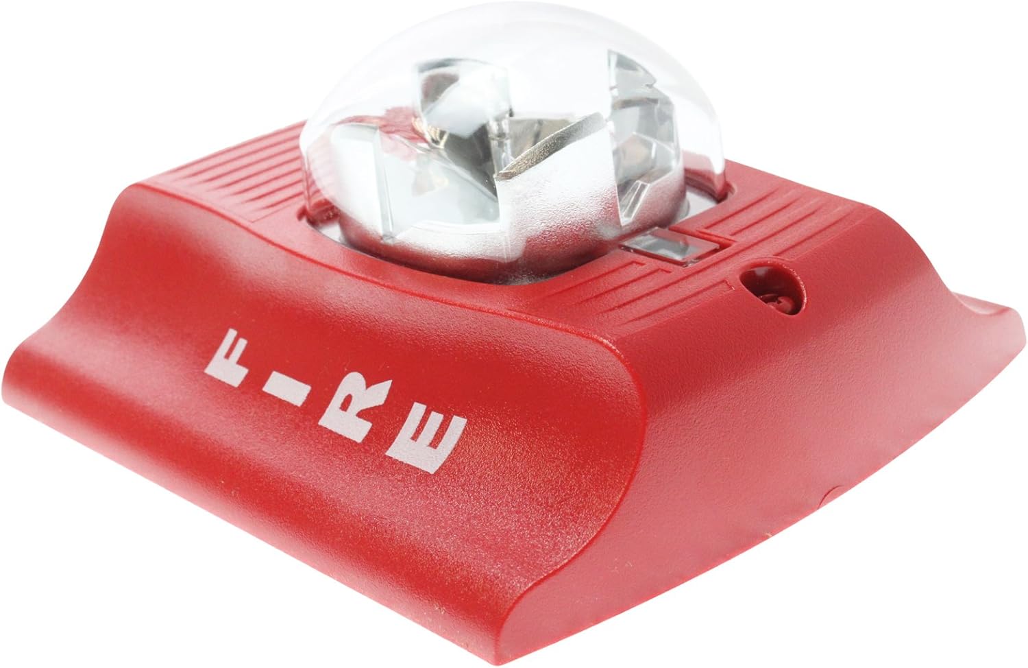
Figura 2: Ġenb view of the System Sensor SR SpectrAlert strobe. This image provides a perspective of the unit's depth and the design of its mounting base.
3. Istruzzjonijiet Operattivi
Once properly installed and connected to a compatible fire alarm control panel, the System Sensor SR SpectrAlert strobe will operate automatically upon activation of the alarm system. The strobe is designed to provide a clear visual warning signal in the event of a fire or other emergency requiring evacuation.
3.1 Operazzjoni Normali
Under normal conditions, the strobe remains inactive. It draws minimal supervisory current from the alarm panel to ensure its readiness.
3.2 Attivazzjoni ta' Allarm
When the fire alarm control panel detects an alarm condition, it will send a signal to the SpectrAlert SR strobe. The strobe will then begin to flash at its pre-selected candela intensity, providing a highly visible warning. The flash rate is typically synchronized with other strobes in the system if connected to a compatible synchronization module.
4. Manutenzjoni
Regular maintenance ensures the continued reliability and performance of your System Sensor SR SpectrAlert strobe. Adhere to the following guidelines:
- Spezzjoni Viżwali: Periodically inspect the strobe for any signs of physical damage, discoloration, or obstruction of the lens. Ensure the unit is securely mounted.
- Tindif: Gently clean the lens and exterior casing b'artab, damp cloth. Do not use abrasive cleaners or solvents, as these can damage the plastic components.
- Ittestjar Funzjonali: Conduct periodic functional tests in accordance with local fire safety regulations and the alarm system manufacturer's recommendations. This typically involves activating the alarm system to verify the strobe flashes correctly.
- Kundizzjonijiet Ambjentali: Ensure the operating environment remains within the specified ambient temperature limits (32 to 120 Degrees F) and humidity range (10-93% non-condensing) to prevent premature failure.
5 Issolvi l-problemi
If your System Sensor SR SpectrAlert strobe is not functioning as expected, consider the following common issues and their potential solutions:
5.1 Strobe Not Flashing
- Ebda Qawwa: Verify that the strobe is receiving adequate power (12-24V) from the alarm panel. Check wiring connections for continuity and proper termination.
- Wiring Skorrett: Ensure the strobe is wired correctly to the alarm panel's notification appliance circuit (NAC) terminals. Refer to the alarm panel's installation manual for specific wiring diagrams.
- Alarm Panel Issue: Confirm that the alarm panel is in an active alarm state and its NAC is functioning correctly. Test other devices on the same circuit if possible.
- Device Failure: If all other checks pass, the strobe unit itself may be faulty and require replacement.
5.2 Incorrect Flash Intensity
- Candela Setting: Re-check the candela selection switch on the strobe unit to ensure it is set to the desired intensity (15, 15/75, 30, 75, 95, 110, or 115 cd).
- Voltage Drop: Vol eċċessivtage drop on the circuit can affect strobe intensity. Ensure wire gauge is appropriate for the circuit length and load.
If troubleshooting steps do not resolve the issue, contact a qualified fire alarm technician for assistance.
6. Speċifikazzjonijiet
| Karatteristika | Dettall |
|---|---|
| Tip ta' Prodott | Wall-Mount Selectable Strobe |
| Numru tal-Mudell | SR |
| Finish Kulur | Aħmar |
| Immuntar | Wall Mounting, Includes Universal Mounting Plate |
| Alarm Current (DC Max) | 66mA - 210mA |
| Flash (Candela) | 15, 15/75, 30, 75, 95, 110, 115 (Selectable) |
| Voltage | 12-24V (8 to 17.5 V for 12V nominal; 16 to 33 V for 24V nominal) |
| Regolazzjoni tal-Qawwa | Regulated 12DC/FWR or regulated 24DC/FWR |
| Limiti tat-Temperatura Ambjentali | 32 to 120 Degrees F (0 to 49 Degrees C) |
| Medda ta 'Umdità | 10-93% li ma jikkondensawx |
| Dimensjonijiet tal-Prodott (L x W x H) | 4.75 x 4.75 x 5.63 pulzieri |
| Piż tal-oġġett | 6.4 uqija |
| Manifattur | Sensor tas-Sistema |


