
1. Introduzzjoni
This manual provides essential information for the safe and efficient operation of your VOTOL EM100SP 72350 Brushless DC Motor Controller. This intelligent programmable controller is designed for electric motorcycles and mobility scooters, supporting motors from 2000W to 3000W and operating within a voltage firxa ta '48V sa 72V.
Please read this manual thoroughly before installation and use to ensure proper functionality and to prevent damage to the controller or connected components.
2. Informazzjoni dwar is-Sigurtà
- Always disconnect power before performing any installation, maintenance, or wiring tasks.
- Ensure all connections are secure and correctly polarized to prevent short circuits or damage.
- Do not expose the controller to water, excessive moisture, or extreme temperatures beyond its operating limits (up to 60°C).
- L-installazzjoni għandha titwettaq minn persunal kwalifikat jekk m'intix ċert dwar xi passi.
- Verify that the controller's voltage and current ratings match your motor and battery specifications.
3. Kontenut tal-Pakkett
Malli tiftaħ il-pakkett, jekk jogħġbok ivverifika li l-komponenti kollha huma preżenti:
- VOTOL EM100SP 72350 Controller
- Matching Wiring Harness
- USB Debugging Data Cable

Image 3.1: The VOTOL EM100SP 72350 controller shown with its accompanying wiring harness.
4. Speċifikazzjonijiet
| Isem tal-Mudell | EM100SP 72350 |
| Voltage Firxa | 48V to 72V (Universal) |
| Maximum Release Current | 150A |
| Phase Line Current | 350A |
| Adaptive Motor Power | 2000W sa 3000W |
| Materjal | Metall, plastik |
| Temperatura operattiva | Sa 60°C |
| Dimensjonijiet | 7.87 x 4.72 x 3.94 pulzieri (Dimensjonijiet tal-Pakkett) |
The controller features weak magnetic technology, which contributes to increased power and speed.
5. Setup u Installazzjoni
Proper installation is crucial for the performance and longevity of your controller. Refer to the following steps and diagrams for guidance.
5.1 Kontrollur Overview

Immaġni 5.1: Fuq view of the EM100SP 72350 controller. Note the main power terminals (B+, U, V, W, B-) and various signal connectors.

Immaġni 5.2: Dettaljata view of the main power terminals (B+, U, V, W, B-) on the controller. Ensure correct wiring for battery positive (B+), motor phases (U, V, W), and battery negative (B-).

Stampa 5.3: View of the main power terminals with the protective cover removed, showing the screw terminals for secure connections.
5.2 Konnessjonijiet tal-Wiring
Connect the controller to your electric vehicle's battery, motor, and other components using the provided wiring harness. Pay close attention to the color coding and pin assignments.
- Konnessjoni tal-batterija: Connect the main battery positive (B+) and negative (B-) terminals to the corresponding ports on the controller.
- Wajers tal-Fażi tal-Mutur: Connect the U, V, W phase wires from your motor to the respective U, V, W terminals on the controller.
- Wajers tas-Sensor Hall: Connect the motor's Hall sensor wires to the Hall Plug on the controller.
- Throttle: Connect the throttle (0-5V) signal wire.
- Brake Signals: Connect Low Brake (0V) and High Brake (12V) wires as per your vehicle's braking system.
- Tqabbid: Qabbad il-wajer tal-ignition.
- Meter Wire: Connect the One-line/Hall Meter Wire for display feedback.
- Port tal-Programmazzjoni: Use the USB Debugging Data Cable to connect to a computer for programming.
Always double-check all connections before applying power. Incorrect wiring can lead to severe damage.
6. Istruzzjonijiet Operattivi
The VOTOL EM100SP 72350 controller offers a range of programmable functions to optimize your vehicle's performance. The default functions include:
- Hall Plug
- Funzjoni Reverse
- Low Brake 0V
- Throttle (0-5V)
- High Brake 12V
- Tqabbid
- One-line/Hall Meter Wire
- Port tal-Programm
- Three Speed Modes
- Mudell Sportiv
- Parking Function
- Kontra s-Serq
- Regen Charge (Regenerative Braking)
- Flux Weaken Current
6.1 Programmazzjoni tas-Softwer
The controller is intelligent and programmable via a dedicated software interface. Use the USB Debugging Data Cable to connect the controller to a computer. The software allows for fine-tuning of various parameters.

Image 6.1: Software interface - Basic Settings. Here you can adjust parameters such as Battery Voltage, Undervoltage, Overvoltage, Busbar Current, Phase Current, and Throttle settings.

Image 6.2: Software interface - Sport Mode and Flux-Weakening. This section allows configuration of current limiting, flux weakening values, three-speed modes (Low, Mid, High), and downhill electric brake assist (HHC/HDC).
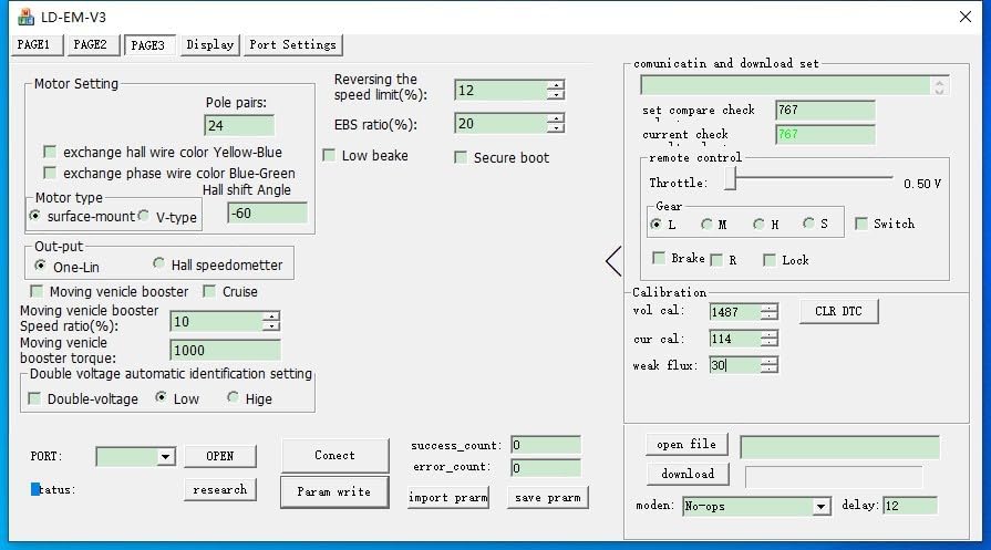
Image 6.3: Software interface - Motor Setting. Configure motor-specific parameters like pole pairs, EBS ratio, Hall shift angle, and output type (One-Lin, Hall speedometer).
Refer to the software's built-in help or specific programming guides for detailed explanations of each parameter. Incorrect settings can affect performance or damage components.
6.2 Dimostrazzjoni bil-Vidjo
Vidjo 6.1: Overview of the VOTOL EM50SP controller, demonstrating its features and potential applications in electric vehicles. While the video shows an EM50SP, the general principles and connectivity are similar to the EM100SP.
7. Manutenzjoni
- Żomm il-kontrollur nadif u ħieles mit-trab u l-fdalijiet.
- Spezzjona regolarment il-konnessjonijiet tal-wajers kollha għal issikkar u sinjali ta' xedd jew korrużjoni.
- Ensure adequate airflow around the controller to prevent overheating, especially during high-power operation.
- Avoid exposing the controller to harsh chemicals or solvents.
8 Issolvi l-problemi
| Problema | Kawża Possibbli | Soluzzjoni |
|---|---|---|
| Kontrollur mhux mixgħul | No power from battery; incorrect wiring; blown fuse (if applicable) | Iċċekkja l-volum tal-batterijatage; verify all power connections; inspect fuses. |
| Motor not responding to throttle | Throttle not connected; faulty throttle; Hall sensor issue; motor wiring incorrect | Check throttle connection and function; inspect Hall sensor wiring; verify motor phase connections. |
| Erratic motor behavior | Incorrect motor parameters in software; loose connections; Hall sensor interference | Review software settings (Image 6.3); check all wiring; ensure Hall sensors are properly seated. |
| Is-sħana żejda | Insufficient cooling; excessive load; incorrect current settings | Ensure proper ventilation; reduce load; check current limits in software (Image 6.2). |
For issues not listed here, or if troubleshooting steps do not resolve the problem, please contact customer support.
9. Garanzija u Appoġġ
This product is covered by a standard manufacturer's warranty. Please refer to your purchase documentation for specific warranty terms and conditions. For technical support, replacement parts, or warranty claims, please contact the retailer or manufacturer directly.
When contacting support, please have your product model number (EM100SP 72350) and purchase date available.