
1. Introduzzjoni
This manual provides detailed instructions for the HGLRC ELRS 915MHz Nano Receiver. This compact receiver is designed for FPV racing drones, offering long-range communication and stable signal performance. It operates on the 915MHz frequency band and utilizes the ExpressLRS (ELRS) communication protocol.
2. Karatteristiċi tal-prodott
- Stronger Diffraction Capability: Ensures good stability even in environments with dense obstacles.
- Extended Flight Distance: Capable of remote control distances exceeding 10 kilometers in actual measurements.
- Għażliet ta' Konnessjoni Flessibbli: Supports both direct plug-in and welding connections to suit various application requirements.
- Stable ELRS Firmware: Utilizes the stable 3.3.0 ELRS firmware, compatible with most remote controllers and high-frequency heads equipped with ELRS scripts.
3. X'hemm fil-Kaxxa
- HGLRC ELRS 915MHz receiver × 1
- HGLRC 915 T-type antenna × 1
- 4pin cable for receiver × 1
4. Speċifikazzjonijiet
| Isem | HGLRC ELRS 915MHz receiver |
| Ċippa | SX1276 |
| Frekwenza | 915MHz |
| Protokoll ta' Komunikazzjoni | CRSF |
| Ħidma Voltage | 3.3V-5V |
| ELRS Firmware Version | 3.3.0 |
| Interface tal-antenna | IPEX1 generation |
| Daqs | 21mm × 11mm |
| Piż | 0.9g (mingħajr antenna) |
| Dimensjonijiet tal-Prodott | 0.01 x 0.01 x 0.01 pulzieri |
| Piż tal-oġġett | 0.317 uqija |
5. Setup
5.1 Riċevitur Overview and Interface Definition
The HGLRC ELRS 915MHz Nano Receiver features a compact design with clearly marked interfaces for easy integration into your FPV system. The status indicator provides visual feedback on the receiver's operational state.

Immaġni: Dettaljata view of the receiver showing the status indicator, IPEX1 antenna connector, and pinout for RX, TX, 5V, and GND.
5.2 Għażliet ta' Konnessjoni
The receiver offers versatility in connection methods, allowing for either direct plug-in using the provided 4-pin cable or soldering directly to your flight controller. Choose the method that best suits your build and skill level.

Image: Illustration showing both direct plug-in and solder pad connection options for the receiver.
5.3 Dijagramma tal-Wiring
Proper wiring is crucial for the correct operation of your receiver. Connect the receiver to your flight controller according to the diagram below. Ensure that GND connects to Ground, 5V to 5V, TX (Transmitter) from the receiver to RX (Receiver) on the flight controller, and RX (Receiver) from the receiver to TX (Transmitter) on the flight controller.

Image: A detailed wiring diagram illustrating how to connect the HGLRC ELRS 915MHz receiver to a flight controller, showing pin assignments for GND, 5V, TX, and RX.
5.4 Binding Procedure (ELRS 3.3.0 Firmware)
The HGLRC ELRS 915MHz receiver comes pre-installed with ELRS firmware version 3.3.0. To bind the receiver to your ELRS transmitter module, follow these general steps:
- Ensure your ELRS transmitter module is also running ELRS firmware version 3.3.0 or compatible.
- Power on your flight controller (with the receiver connected) three times, cycling power quickly. The receiver's LED should flash rapidly, indicating it is in bind mode.
- Alternatively, if your flight controller is connected to Betaflight, you can use the ELRS Lua script on your transmitter to initiate binding. Navigate to the ELRS script, select 'Bind', and then power cycle the receiver.
- Once the receiver is in bind mode, activate the bind function on your ELRS transmitter module.
- A successful bind is indicated by a solid LED on the receiver.
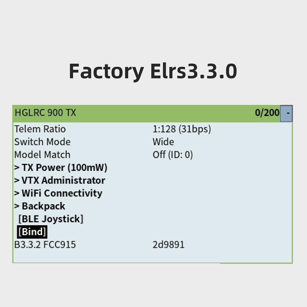
Immaġni: Eksample screen from an ELRS transmitter module showing firmware version 3.3.0 and a 'Bind' option, indicating software-based binding capability.
5.5 Installazzjoni tal-antenna
Connect the provided T-type antenna to the IPEX1 connector on the receiver. Ensure the connection is secure. Position the antenna away from carbon fiber frames and other electronic components for optimal signal reception.

Image: The HGLRC ELRS 915MHz Nano Receiver with its T-type antenna connected, highlighting its long-range communication capability.
6. Joperaw
Once successfully bound and integrated into your FPV system, the HGLRC ELRS 915MHz Nano Receiver will provide reliable control and telemetry data. Always perform a range check before flying, especially after any changes to your setup. Monitor your signal quality (RSSI/LQ) during flight to ensure safe operation.
The compact size of the receiver (21mm x 11mm) allows for flexible placement within your drone, but ensure it is not obstructed by conductive materials.
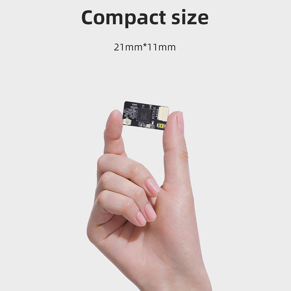
Image: A hand holding the HGLRC ELRS 915MHz Nano Receiver, demonstrating its compact dimensions of 21mm by 11mm.
7. Manutenzjoni
- Spezzjoni Fiżika: Regularly check the receiver and antenna for any signs of damage, such as bent pins, frayed wires, or cracks in the PCB.
- Indafa: Keep the receiver free from dust, dirt, and moisture. Use a soft, dry brush or compressed air for cleaning. Avoid using liquids.
- Kura tal-antenna: Ensure the antenna is securely attached and not kinked or damaged. A damaged antenna can significantly reduce range and signal quality.
- Aġġornamenti tal-Firmware: Periodically check the official HGLRC or ExpressLRS website for firmware updates. Updating firmware can improve performance, add features, or fix bugs. Follow official instructions carefully when updating.
8 Issolvi l-problemi
- Ebda Qawwa/LED Mitfi:
- Check all power connections (GND, 5V) to ensure they are correctly wired and receiving power.
- Verify the working voltage is within the specified 3.3V-5V range.
- Riċevitur Mhux Vinkolanti:
- Ensure both the receiver and transmitter module are running compatible ELRS firmware versions (e.g., 3.3.0).
- Confirm the power cycling method for bind mode (three quick power cycles) is performed correctly.
- Check for correct wiring of TX/RX lines between the receiver and flight controller if using Betaflight passthrough for binding.
- Poor Range/Signal Loss:
- Inspect the antenna for damage or improper connection to the IPEX1 port.
- Ensure the antenna is positioned optimally, away from carbon fiber, batteries, or other electronics that could shield the signal.
- Verify the transmitter power output settings.
- Iċċekkja għal interferenza RF lokali.
- Kwistjonijiet ta' Telemetrija:
- Confirm the TX/RX wiring is correct between the receiver and flight controller. Incorrect wiring can lead to telemetry data not being transmitted or received.
- Ensure telemetry is enabled in your flight controller's configuration (e.g., Betaflight).
- Incorrect Wire Harness:
- Some users have reported that the included wire harness may have reversed pin assignments. Always verify the pinout (GND, 5V, TX, RX) against the receiver's markings and your flight controller's documentation before connecting. If necessary, re-pin the connector or solder directly.
9. Garanzija u Appoġġ
For warranty information and technical support, please refer to the official HGLRC webis-sit jew ikkuntattja lill-bejjiegħ bl-imnut li mingħandu xtrajt il-prodott. Żomm il-prova tax-xiri tiegħek għal kwalunkwe talba ta' garanzija.