1. Introduzzjoni
This manual provides instructions for the WWZMDIB CH341A EEPROM BIOS Programmer. This device is designed for backing up, erasing, programming, and calibrating various software and is compatible with most 24 and 25 series SOP8 and SOP16 chips. It supports both CH341A and CH341B chips.
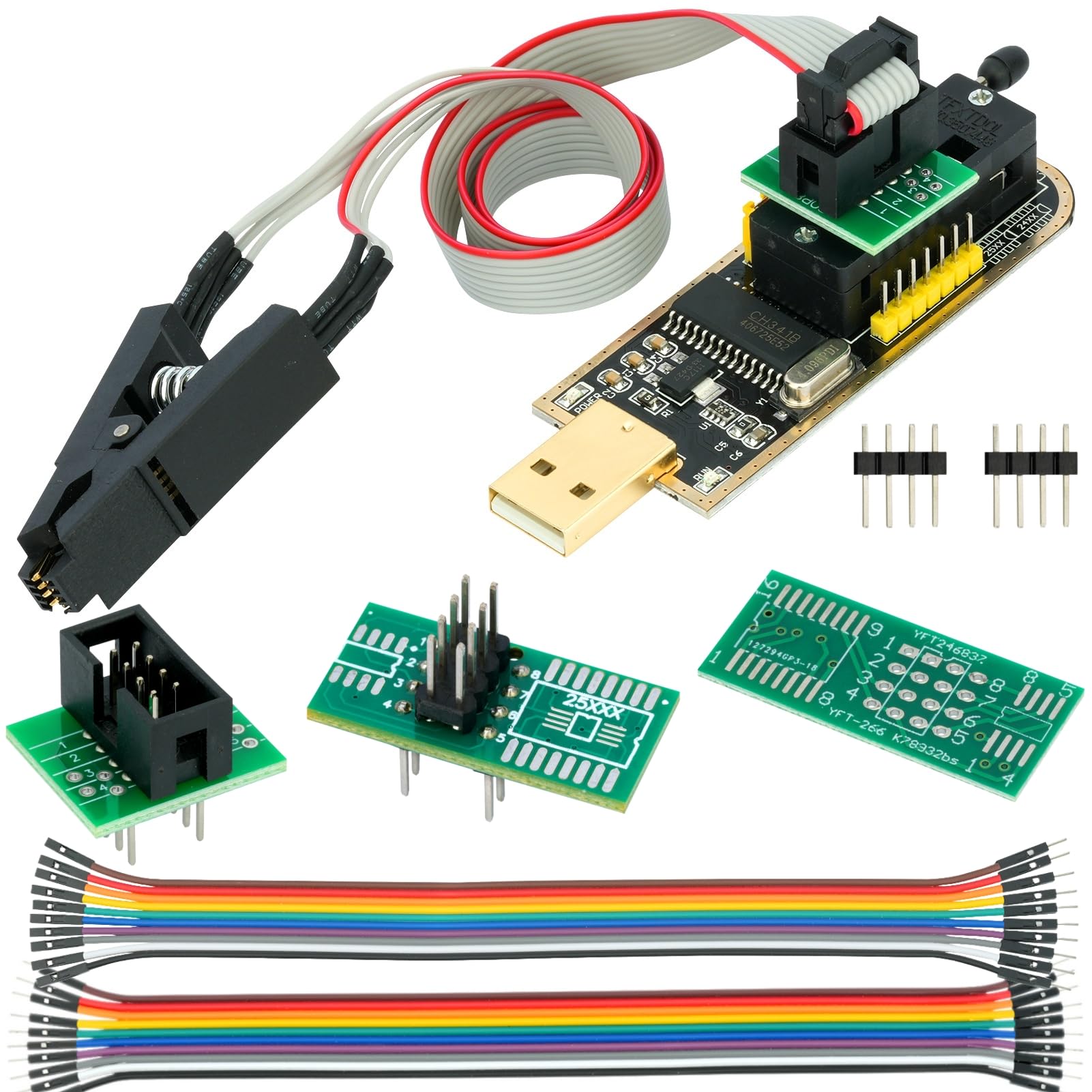
Immaġni 1.1: Fuqview of the WWZMDIB CH341A EEPROM BIOS Programmer kit.
2. X'hemm fil-Kaxxa
The WWZMDIB CH341A EEPROM BIOS Programmer kit typically includes the following components:
- IC Test Clip
- USB Programmer (CH341A module)
- Converter (likely SOP8/SOP16 conversion plate)
- Wajer DuPont
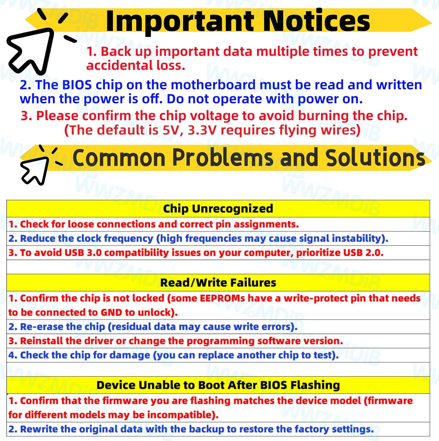
Image 2.1: Contents of the WWZMDIB CH341A Programmer package.
3. Avviżi Importanti
Adhere to the following important notices to ensure safe and correct operation of the programmer:
- Back up important data multiple times to prevent accidental loss.
- The BIOS chip on the motherboard must be read and written when the power is off. Do not operate with power on.
- Confirm the chip voltage to avoid burning the chip. The default voltage is 5V; 3.3V operation requires specific wiring (flying wires).

Image 3.1: Important operational guidelines for the programmer.
4. Setup u Konfigurazzjoni
4.1. 3.3V Power Supply Setting Method
For chips requiring 3.3V, specific modifications are necessary:
- Connect pins 28 and 9 to 3.3V.
- Pin 28 must be disconnected from its original 5V supply. Use insulating tape to ensure proper isolation.

Image 4.1: Instructions for configuring the programmer for 3.3V operation.
4.2. Jumper Cap Interface Conversion
The CH341A programmer can convert a USB port to a TTL serial port. Configure the jumper caps for the desired function:
- For programming, set the jumper cap to positions 1-2.
- For TTL serial communication, set the jumper cap to positions 2-3.
- Ensure correct pin assignments for 24 Series and 25 Series chips as indicated on the board. Pay attention to the pin order (1-8).

Image 4.2: Jumper cap settings for programming and TTL serial port conversion.
4.3. Connecting the SOIC8 Clip
The SOIC8 test clip is used for in-circuit programming without soldering:
- The cable length of the clip is approximately 13.77 inches (35 cm).
- It is designed for 1.27mm pitch SOP8 chips.
- The red cable on the clip indicates pin 1 for correct positioning on the chip.

Image 4.3: Details of the SOIC8 test clip for chip connection.
5. Istruzzjonijiet Operattivi
The CH341A programmer facilitates various operations on EEPROM and BIOS chips. Ensure the chip voltage is confirmed (3.3V or 5V) before proceeding to prevent damage.
- Connect the Programmer: Insert the CH341A programmer into a USB port on your computer.
- Connect the Chip: Use the SOIC8 clip or appropriate conversion plate to connect the target chip to the programmer. Ensure the red cable on the clip aligns with pin 1 of the chip. No soldering is required for the clip connection.
- Installa Sewwieqa u Software: Install the necessary drivers for the CH341A and compatible programming software (e.g., AsProgrammer, CH341A Programmer software).
- Select Chip Type: In the programming software, select the correct chip manufacturer and model (e.g., 24 Series, 25 Series).
- Read Chip Data: Before any write operation, always read the existing data from the chip and save it as a backup file. This is crucial for recovery in case of errors.
- Erase Chip: If writing new data, perform an erase operation on the chip as required by the software.
- Program Chip: Load the desired firmware or data file into the software and initiate the programming process.
- Ivverifika d-Data: After programming, verify the written data against the source file biex tiġi żgurata l-eżattezza.
6. Supported Chips
The WWZMDIB CH341A programmer supports a wide range of 24 and 25 series EEPROM and Flash chips. Refer to the image below for a detailed list of compatible chips from various manufacturers.

Image 6.1: Comprehensive list of supported 25 Series and 24 Series chips.
7 Issolvi l-problemi
This section addresses common issues encountered during the use of the CH341A programmer.
7.1. Chip Unrecognized
- Check for loose connections and ensure correct pin assignments.
- Reduce the clock frequency in the software, as high frequencies can cause signal instability.
- Prioritize using a USB 2.0 port to avoid compatibility issues that may arise with USB 3.0.
7.2. Read/Write Failures
- Confirm that the chip is not locked. Some EEPROMs have a write-protect pin that needs to be connected to GND to unlock.
- Re-erase the chip. Residual data can cause write errors.
- Reinstall the driver or try a different version of the programming software.
- Check the chip for physical damage. If possible, test with another chip.
7.3. Device Unable to Boot After BIOS Flashing
- Confirm that the firmware being flashed matches the device model. Incompatible firmware can prevent booting.
- Rewrite the original data using the backup created before flashing to restore factory settings.
8. Speċifikazzjonijiet
| Brand | WWZMDiB |
| Numru tal-Mudell tal-Oġġett | Programmatur |
| Kompatibilità tas-Sistema Operattiva | Windows 10 (and likely other Windows versions) |
| Piż tal-oġġett | 2.08 uqija (0.06 Kilogrammi) |
| Dimensjonijiet tal-Pakkett | 5.28 x 2.6 x 0.91 pulzieri |
| Interface tal-Ħardwer | USB |
| Apparati Kompatibbli | Multiple Devices (24/25 series SOP8/SOP16 chips) |
9. Manutenzjoni
To ensure the longevity and proper functioning of your WWZMDIB CH341A EEPROM BIOS Programmer, follow these maintenance guidelines:
- Ħażna: Store the programmer and its accessories in a dry, dust-free environment when not in use.
- Immaniġġjar: Handle the device with care. Avoid dropping or subjecting it to physical shocks, as this can damage internal components or connections, especially the USB-A connector's welding spots.
- Tindif: Uża drapp artab u niexef biex tnaddaf l-apparat. Tużax prodotti tat-tindif likwidi jew solventi.
- Konnessjonijiet: Regularly inspect the SOIC8 clip and conversion plates for any signs of wear or damage. Ensure the pins are clean and straight for reliable contact.
10. Garanzija u Appoġġ
For specific warranty information and technical support, please refer to the documentation provided with your purchase or contact WWZMDiB customer service through the platform where the product was acquired. Ensure you retain your proof of purchase for any warranty claims.