
1. Introduzzjoni
This manual provides comprehensive instructions for the installation, operation, and maintenance of the STEPPERONLINE DM320T Digital Stepper Driver. This driver is designed for use with Nema 8, 11, 14, 16, and 17 stepper motors, offering precise control with micro-step resolutions and adjustable current settings.
Jekk jogħġbok aqra dan il-manwal bir-reqqa qabel ma tħaddem l-apparat biex tiżgura l-funzjonalità u s-sigurtà xierqa.
2. Karatteristiċi ewlenin
- Industrial-grade stepper driver for reliable performance.
- Adjustable current output from 0.3A to 2.2A (peak).
- Micro-step resolutions up to 1/64 for smooth motor operation.
- Compatible with Nema 8, 11, 14, 16, and 17 stepper motors.
- Input voltagFirxa e: 10-30VDC.
- Built-in protection functions for over-current and over-voltage.
3. Speċifikazzjonijiet
3.1 Speċifikazzjonijiet elettriċi

This image displays the electrical specifications for the DM320T driver, including output current (Min 0.3A, Max 2.2A Peak), supply voltage (10-30VDC), logic signal current (7-16mA), pulse input frequency (0-60kHz), minimal pulse width (7.5µs), minimal direction setup (7.5µs), and isolation resistance (100 MΩ).
3.2 Operating Environment and Other Specifications

This image details the operating environment and other specifications. It covers cooling requirements (natural or forced), ambient temperature (0°C to 65°C), humidity (40%-90%RH), operating temperature (0°C to 50°C), storage temperature (-20°C to 65°C), and weight (approx. 90g).
3.3 Speċifikazzjonijiet mekkaniċi

This image illustrates the mechanical dimensions of the DM320T driver, showing measurements in millimeters. It also recommends side mounting for improved heat dissipation.
4. Setup u Wiring
Proper wiring is crucial for the safe and effective operation of the DM320T driver. Ensure all connections are secure before applying power.
4.1 Driver Overview

Din l-immaġni turi l-parti ta’ fuq view of the DM320T driver, highlighting the DIP switches for current and micro-step settings, along with the terminal blocks for power, motor, and control signals.
4.2 Wiring Diagram Example
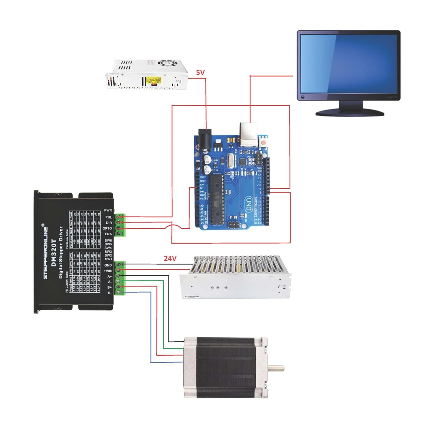
This diagram illustrates a typical wiring setup for the DM320T driver, connecting it to an Arduino board, a 24V power supply for the motor, a 5V power supply for the Arduino, and a stepper motor. Ensure correct polarity for power connections and proper signal routing for PUL (Pulse), DIR (Direction), and ENA (Enable) inputs.
4.3 Current and Micro-step Settings
The DM320T driver features a 6-bit DIP switch for configuring the output current and micro-step resolution. Switches SW1-SW3 control the peak current, and SW4-SW6 control the pulses per revolution (micro-step resolution).

This image shows the DIP switch configuration table. Refer to this table to set the desired peak current and micro-step resolution for your application. For example, setting SW1 'on', SW2 'off', SW3 'on' corresponds to a 1.0A peak current. Setting SW4 'on', SW5 'off', SW6 'on' corresponds to 1600 pulses/rev.
Importanti: Always adjust DIP switches when the power is off to prevent damage to the driver or motor.
5. Operazzjoni
After completing the wiring and setting the DIP switches, the driver is ready for operation.
- Qawwa Mixgħul: Applika l-enerġija lis-sewwieq fil-volum speċifikattage firxa (10-30VDC).
- Sinjali ta' Kontroll: Provide pulse (PUL) and direction (DIR) signals from your controller (e.g., Arduino, PLC).
- Enable (ENA): The ENA input can be used to enable or disable the motor. By default, if unconnected, the driver is enabled. Connecting ENA to a high signal (e.g., +5V) will enable the driver, while a low signal or open circuit might disable it depending on the specific configuration. Some users report needing to explicitly connect ENA to +5V for operation.
- Motor Movement: The motor will move according to the pulse signals received. The direction is determined by the DIR signal.
For optimal performance, ensure your control signals are clean and within the specified logic signal current range.
6. Manutenzjoni
The DM320T driver is designed for low maintenance. However, periodic checks can extend its lifespan and ensure reliable operation:
- Kundizzjonijiet Ambjentali: Ensure the operating environment remains within the specified temperature and humidity ranges. Avoid dust, oil fog, and corrosive gases.
- Tkessiħ: While the driver supports natural cooling, forced cooling (e.g., a fan) is recommended in applications with high current settings or limited airflow to prevent overheating.
- Konnessjonijiet: Periodically check all wiring connections for tightness and integrity. Loose connections can lead to intermittent operation or damage.
- Tindif: Keep the driver free from dust and debris. Use a soft, dry cloth for cleaning.
7 Issolvi l-problemi
This section provides solutions to common issues encountered during the operation of the DM320T driver.

This image presents a troubleshooting guide. It lists common symptoms such as motor not rotating, motor rotating in the wrong direction, erratic motor motion, motor stalling, and excessive heating, along with their possible causes and solutions.
| Sintomu | Problemi Possibbli |
|---|---|
| Il-mutur mhux qed idur | No power; Fault condition exists; The drive is disabled. |
| Il-mutur idur fid-direzzjoni ħażina | Motor phases may be connected in reverse; DIP switch current setting is wrong. |
| The drive is in fault | Something wrong with motor coil. |
| Moviment erratiku tal-mutur | Control signal is too weak; Control signal is interfered; Wrong motor connection; Something wrong with motor coil. |
| Postijiet bil-mutur waqt l-aċċelerazzjoni | Current setting is too small, losing steps; Acceleration is set too high; Power supply voltage baxx wisq. |
| Tisħin eċċessiv tal-mutur u s-sewqan | Inadequate heat sinking / cooling; Automatic current reduction function not being utilized; Current is set too high. |
7.1 Protection Functions and Alarm Light

This image details the protection functions of the DM320T driver. The red LED on the driver indicates fault conditions through specific blink patterns:
- 1 Blink: Over-current protection activated (peak current exceeds limit).
- 2 Blinks: Vol-żejjedtage protection activated (drive working voltage > 34VDC).
- 3 Blinks: Riżervat.
When protection functions are active, the motor shaft will be free, or the red LED will blink. To reset the drive, remove power, address the underlying problem, and then reapply power.
8. Garanzija u Appoġġ
STEPPERONLINE products are manufactured to high quality standards. For warranty information and technical support, please refer to the official STEPPERONLINE webis-sit jew ikkuntattja lis-servizz tal-konsumatur tagħhom direttament. Żomm l-irċevuta tax-xiri tiegħek għal talbiet ta' garanzija.
Għal aktar riżorsi u informazzjoni dwar il-prodott, żur il- STEPPERONLINE Store on Amazon.